Earthquake isolation and reduction structure and earthquake reduction method thereof

A technology of shock isolation and rubber bearing, applied in bridge parts, erection/assembly of bridges, bridges, etc., can solve the problems of unsatisfactory shock absorption effect and high construction cost, and achieve the improvement of the level of building industrialization, the force is clear, and the production is simple. Effect

Pending Publication Date: 2017-01-25
SHANGHAI MUNICIPAL ENG DESIGN INST GRP
View PDF0 Cites 5 Cited by
  • Summary
  • Abstract
  • Description
  • Claims
  • Application Information

AI Technical Summary

Problems solved by technology

[0007] Aiming at the problem of unsatisfactory shock-absorbing effect or high cost in the current shock-absorbing and isolation methods of long-span low-pier continuous girder bridges, the present invention provides a simple-structured, cost-saving shock-absorbing and isolating structure and a shock-absorbing method to reduce bridge Seismic force of the upper structure on the lower structure, and control the horizontal displacement of the beam

Method used


Image

  • Earthquake isolation and reduction structure and earthquake reduction method thereof

Examples


Embodiment 1

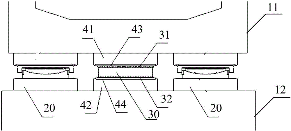
[0024] see figure 1 , a shock-absorbing and isolating structure, including several spherical bearings 20 arranged at intervals between the upper and lower structures (11, 12) of the bridge, at least one rubber bearing (not shown) arranged side by side at adjacent intervals Between the spherical bearings 20, the rubber bearings from top to bottom are an upper cushion block 41, a rubber bearing body 30 and a lower cushion block 42, and the top and bottom ends of the rubber bearing body 30 are respectively provided with upper and lower supports. Seat steel plate (31,32), upper and lower support steel plate (31,32) and corresponding upper and lower spacer (41,42) are respectively provided with upper and lower spacer steel plate (43,44), upper , Lower pad steel plates (43,44) are embedded in the upper and lower pads (41,42). Specifically, by arranging a plurality of spherical bearings 20 between the upper and lower structures (11, 12) of the long-span low-pier continuous girder br...

Embodiment 2

[0030] read on figure 1 , the present embodiment discloses a shock absorbing method utilizing the shock absorbing and isolating structure of the present invention, comprising the following steps:

[0031] Step 1: fixedly connect the spherical bearing 20 and the rubber bearing between the upper and lower structures (11, 12) of the bridge, and make the spherical bearing 20 and the rubber bearing arranged side by side at intervals;

[0032] Step 2: When an earthquake occurs and the lateral force exceeds the horizontal seismic force threshold, the spherical bearing 20 is sheared, and the rubber bearing and the upper and lower bearing steel plates (31, 32) at the upper and lower ends of the rubber bearing do not slide relative to each other. Therefore, the rubber bearing and the spherical bearing 20 jointly bear the horizontal force, reduce the seismic force, realize the control of the horizontal displacement of the girder bridge body, and prevent the damage of the long-span low-pi...


PUM


Abstract

The invention provides a shock-absorbing and isolating structure and a shock-absorbing method thereof, which belong to the technical field of bridge engineering and are used to solve the problems of unsatisfactory shock-absorbing effect or high cost in traditional shock-absorbing and isolating methods. The structure includes a number of spherical bearings and rubber bearings arranged at intervals between the upper structure and the lower structure of the bridge. The top and bottom of the body are respectively equipped with upper and lower support steel plates, and the upper and lower support steel plates and the corresponding upper and lower cushion blocks are respectively provided with upper and lower cushion steel plates, and the upper and lower cushion steel plates are embedded Inside the upper and lower pads. In this damping method, first, the spherical bearing and the rubber bearing are fixedly connected between the upper and lower structures of the bridge, and the spherical bearing and the rubber bearing are arranged side by side; then when an earthquake occurs, the spherical bearing is After shearing, the rubber bearing bears the horizontal force, so as to realize the control of the horizontal displacement of the bridge girder.

Description

technical field [0001] The invention relates to the technical field of bridge engineering, in particular to a shock absorbing and isolating structure and a shock absorbing method thereof. Background technique [0002] Continuous girder bridge refers to a continuous girder bridge with two or more spans, which belongs to the statically indeterminate system. Under the action of constant live load, the negative bending moment of the fulcrum generated by the continuous beam has an unloading effect on the positive bending moment of the mid-span, so that the internal force state is relatively uniform and reasonable, so the beam height can be reduced, thereby increasing the clearance under the bridge, saving materials, and improving rigidity. Large, good integrity, high overload capacity, high safety, less expansion joints on the bridge deck, and because the bending moment of the mid-span section is reduced, the bridge span can be increased. However, due to the weight of the supers...

Claims


Application Information

Patent Timeline
Patent Type & Authority Applications(China)
IPC IPC(8): E01D19/04E01D21/00
CPCE01D19/046E01D19/041E01D21/00
Inventor 马骉李建中王浩任烈柯雷宇王巍伍大成
Owner SHANGHAI MUNICIPAL ENG DESIGN INST GRP
Why Eureka
Try Eureka