An integral walking guardrail template assembly and disassembly machine

A technology of formwork, guardrails, applied in the direction of road safety devices, roads, road repairs, etc.

Active Publication Date: 2018-08-17
岳阳安泰重工科技股份有限公司
View PDF6 Cites 0 Cited by
  • Summary
  • Abstract
  • Description
  • Claims
  • Application Information

AI Technical Summary

Problems solved by technology

[0005] The purpose of the present invention is to solve the defects and problems of manual assembly and disassembly of formwork, and to provide a whole walking guardrail formwork assembly and disassembly machine

Method used


Image

  • An integral walking guardrail template assembly and disassembly machine
  • An integral walking guardrail template assembly and disassembly machine
  • An integral walking guardrail template assembly and disassembly machine

Examples


Embodiment 1

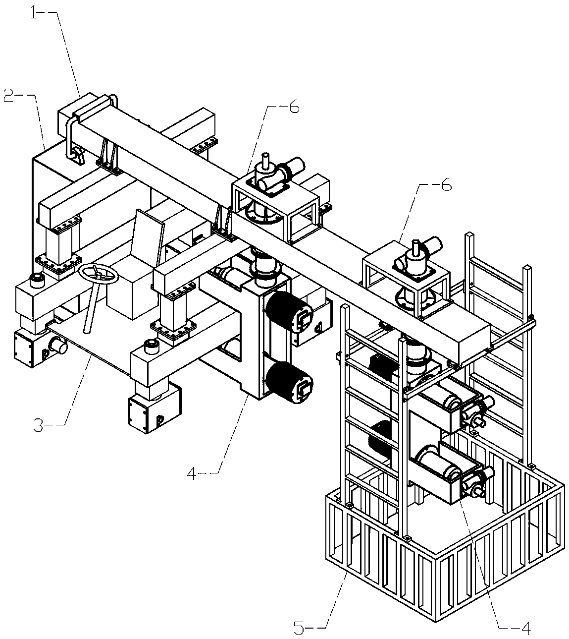
[0031] It can be seen from the content of the invention that a whole walking guardrail template assembly and disassembly machine is composed of main beam 1, counterweight 2, driving control system 3, telescopic cantilever 4, artificial hanging basket 5, and cantilever frame 6; Installed on the left side of the lower part of the main beam 1; the driving control system 3 is installed under the main beam 1; The lower part of beam 1 is on the far right.

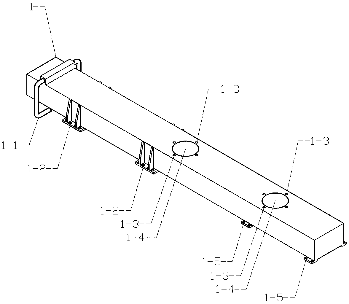
[0032] The main girder 1 of the present invention refers to: the long girder of the main force-bearing member; it is provided with a counterweight installation suspender 1-1, a beam adaptation hole 1-2, a longitudinal guide cylinder adaptation hole 1-3, Adaptive holes 1-4 for the artificial hanging basket, and through holes 1-5 for the longitudinal telescopic cylinder; their function is to carry various loads and transfer them to designated places; its structure is as attached figure 2 As shown, its design position is as attach...

Embodiment 2

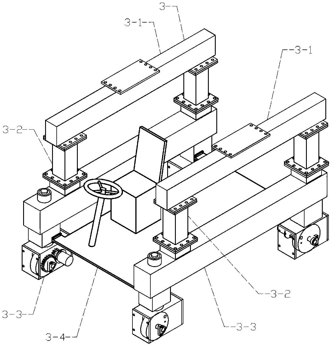
[0039] In order to realize the function of driving equipment and devices to move without completely dismantling the formwork and saving manpower and time, the present invention is provided with a driving control system 3, and a beam 3-1, a support beam 3-2, and a ground beam 3 are arranged on it. -3. The cockpit 3-4; the crossbeam 3-1 is set above the support beam 3-2; the ground beam 3-3, as the load of the whole device, is located at the bottom; the cockpit 3-4 is installed on two ground beams 3 Between -3.

[0040] The crossbeam 3-1 of the present invention refers to: a transverse beam; it is provided with a crossbeam installation hole 3-5 and a support beam adaptation hole 3-6; its function is to support the beam on the main load-bearing member; its structure as attached Figure 4 As shown, its design position is as attached image 3 Shown in Mark 3-1.

[0041]The support beam 3-2 in the present invention refers to: a beam erected; a support beam installation hole 3-7 a...

Embodiment 3

[0045] In order to realize the function of adjusting the required height of the template by adjusting the height in the longitudinal direction, the present invention is provided with a longitudinal screw elevator 4-1 and a longitudinal telescopic cylinder 4-3; Hole 4-7, longitudinal screw elevator connecting seat 4-8; horizontal telescopic frame adaptation hole 4-7 is located at the bottom of longitudinal telescopic tube 4-3; longitudinal screw elevator connecting seat 4-8 is located at the top of longitudinal telescopic tube 4-3 .

[0046] The vertical spiral elevator 4-1 of the present invention refers to: the elevator on the telescopic cantilever 4; Its function is to adjust the lifting of the longitudinal direction according to actual needs; Its design position is as attached Figure 7 Shown in Mark 4-1.

[0047] The longitudinal telescopic cylinder 4-3 of the present invention refers to: the longitudinal telescopic cylinder on the telescopic cantilever 4; it is provided ...


PUM


Abstract

The invention discloses a whole walking parapet template dismantling machine. The whole walking parapet template dismantling machine comprises a girder, a counterweight, a driving control system, a telescopic cantilever, an artificial basket, and a cantilever frame; the whole walking parapet template dismantling machine has no need to dismantle a template completely after installing and dismantling the template, and the whole walking parapet template dismantling machine can also walk as a whole to the next workplace; the designed horizontal spiral elevator and the designed horizontal telescopic cylinder can adjust the height of the template flexibly to a required height by adjusting the height in a longitudinal direction; the designed transverse spiral elevator and the designed transverse telescopic cylinder can also meet the requirement that the template need to move the location by adjusting the length in a transverse direction; at the same time, in order to make the loading of the template convenient, a template claw is designed, and the grasping and placement of the template are facilitated; a plurality of telescopic mechanisms are directly used to implement the complete demolition of the template for the whole mechanism, and the whole set of mechanism can be made into a walking vehicle-mounted type dismantling machine. The operation is convenient, and the complex requirements in a practical work can be met.

Description

Technical field: [0001] The invention relates to a mechanism for installing and disassembling guardrail templates for highway construction, in particular to a machine for installing and disassembling guardrail templates for integral walking. Background technique: [0002] At present, the assembly and disassembly industry of guardrail formwork for highway construction in my country is mainly manual assembly and disassembly of formwork. On-site assembly has the problems of low efficiency, time-consuming and laborious, and easy to cause safety accidents. There have also been some alternative machines, mostly using the principle of leverage. Curve decoupling cannot fully meet the complex needs in actual work, so up to now, there has not been a real automatic assembly and disassembly machine. [0003] At present, in the patent CN202611340U disclosed in the Chinese patent literature, a self-propelled roadbed protection, transportation and installation integrated machine is disclose...

Claims


Application Information

Patent Timeline
Patent Type & Authority Patents(China)
IPC IPC(8): E01F15/00E01C19/50
Inventor 罗振强欧阳州李智龙任杰颜兵杨会谭勇袁湘民彭立雄陈斌
Owner 岳阳安泰重工科技股份有限公司
Why Eureka
Try Eureka