Automatic grouting construction device with high efficiency

A construction device and high-efficiency technology, applied in infrastructure engineering, building material processing, construction, etc., can solve the problems of low mixing efficiency, inconvenient cleaning, inconvenient operation, etc., to facilitate installation and production, and reduce costs. investment, to achieve the effect of grouting efficiency

Inactive Publication Date: 2017-01-25
ZHEJIANG COLLEGE OF CONSTR
View PDF8 Cites 5 Cited by
  • Summary
  • Abstract
  • Description
  • Claims
  • Application Information

AI Technical Summary

Problems solved by technology

For grouting, the method of pressure grouting is adopted, but such a grouting device has disadvantages such as complicated results, inconvenient carrying, difficult maintenance, inconvenient cleaning, and high cost. Therefore, Hebei Union University applied for it on February 15, 2015. No. 201520109887.8 proposes "a simple pressure grouting device", which includes a barrel, a barrel support frame, an air inlet, and a discharge port. A reaction beam fixed to the barrel is installed above the barrel, and the reaction beam The threaded hole in the middle of the crossbeam is equipped with a compression screw, and the upper part of the compression screw is equipped with a rotating handle. Barrel cover
When grouting the grouting device with this structure, the upper cover must be opened first, then the upper cover should be put on the cover, and the round handle should be rotated so that the pressing screw can withstand the upper cover so that the upper cover is sealed with the barrel before proceeding. Operation, the operation is relatively inconvenient, and the stirring efficiency is relatively low, which cannot meet the growing needs of modern people

Method used


Image

  • Automatic grouting construction device with high efficiency
  • Automatic grouting construction device with high efficiency

Examples


Embodiment Construction

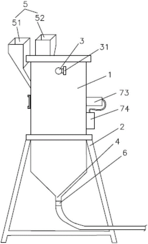
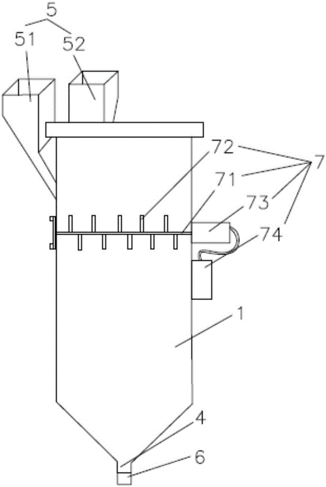
[0012] Such as figure 1 and figure 2 As shown, a high-efficiency automatic grouting construction device includes a barrel 1 and a barrel support frame 2, an air inlet 3 is arranged on the barrel 1, a discharge port 4 is arranged at the bottom of the barrel 1, and the barrel supports The frame 2 is a four-legged support frame welded by angle steel, which is convenient for installation and manufacture. The barrel 1 is connected with a hopper 5, and the hopper 5 is divided into a first hopper 51 and a second hopper 52, and the first hopper 51 and the second hopper 52 They are respectively connected to the barrel 1 through a switch, and the switches are respectively installed at the junction of the first hopper 51 and the barrel 1 and the junction of the second hopper 52 and the barrel 1. The closing of the switch controls whether the slurry in the hopper enters the barrel 1 for mixing, the discharge port 4 is provided with a flow control valve 6 for controlling the flow rate, a...


PUM


Abstract

The invention discloses an automatic grouting construction device with high efficiency. The automatic grouting construction device comprises a material barrel and a material barrel support frame, wherein an air inlet is formed in the material barrel; a discharge hole is formed in the bottom of the material barrel; the material barrel support frame is a four-leg support frame formed by welding angle iron; the material barrel is communicated with hoppers comprising a first hopper and a second hopper; a flow control valve for controlling flow is arranged on the discharge hole; a flow velocity detector for detecting the flow velocity of grouting at the discharge hole is arranged at the position of the flow control valve; the interior of the material barrel is provided with a stirring device; and an air inlet valve for controlling the air inflow of the material barrel is arranged on the air inlet. The automatic grouting construction device is reasonable in design, simple in structure and convenient to install and manufacture; meanwhile, the operation of materials is simpler and more convenient through the first hopper and the second hopper, the materials are also conveniently mixed, and the interior of the material barrel is provided with the stirring device, so that the work efficiency is effectively improved.

Description

technical field [0001] The invention relates to the technical field of engineering grouting equipment, in particular to an automatic grouting construction device with high efficiency. Background technique [0002] The grouting material is made of high-strength material as the aggregate, cement as the binder, and supplemented with high-fluidity, micro-expansion, anti-segregation and other substances. The grouting material has good self-flowing properties, rapid hardening, early strength, high strength, and no Shrinkage, micro-expansion, non-toxic, harmless, non-aging, no pollution to water quality and surrounding environment, good self-tightness, anti-rust and other characteristics, fundamentally change the force of the equipment base, so that it can bear all the equipment evenly Load, so as to meet the installation requirements of various machinery and electrical equipment (heavy equipment high-precision grinder), it is an ideal grouting material in the era of mat-free insta...

Claims


Application Information

Patent Timeline
Patent Type & Authority Applications(China)
IPC IPC(8): E04G21/02E02D15/02
CPCE04G21/02E02D15/02
Inventor 俞慧刚沙玲何春柯张宇豪
Owner ZHEJIANG COLLEGE OF CONSTR
Why Eureka
Try Eureka