Static pressure gas labyrinth throttling control mechanism for dynamic and static pressure dry gas seal

A dry gas sealing, dynamic and static pressure technology, applied in the direction of engine sealing, engine components, mechanical equipment, etc., can solve the problems of complex and changeable working conditions, and achieve the elimination of the increase of the seal end face clearance, the enhancement of the throttling effect, and the throttling. The effect of weakening the effect

Active Publication Date: 2017-12-29
ZHEJIANG UNIV OF TECH
View PDF8 Cites 4 Cited by
  • Summary
  • Abstract
  • Description
  • Claims
  • Application Information

AI Technical Summary

Problems solved by technology

[0003] The formation and stability of the air film on the end face of the dynamic and static pressure dry gas seal is mainly realized by the dynamic pressure opening force generated by the end face dynamic pressure groove and the static pressure opening force provided by the external air supply entering the end face equalizing groove. The working conditions of high-end machinery and equipment in chemical, chemical, metallurgical and pharmaceutical industries are complex and changeable, and the method to deal with changing working conditions is often to adjust the external air supply pressure on the end face. It is this external pressure adjustment that makes the static pressure suddenly change. This puts forward higher requirements for the adaptability and stability of the dynamic and static pressure dry gas seal, but the current technology cannot meet this requirement

Method used


Image

  • Static pressure gas labyrinth throttling control mechanism for dynamic and static pressure dry gas seal
  • Static pressure gas labyrinth throttling control mechanism for dynamic and static pressure dry gas seal

Examples


Embodiment Construction

[0018] The technical solution of the present invention will be described in detail below in conjunction with the accompanying drawings.

[0019] refer to figure 1 with figure 2 :

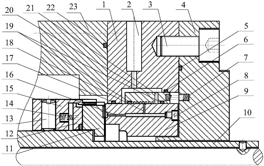
[0020] A static pressure gas labyrinth throttling control mechanism for dynamic and static pressure dry gas seals, the right side of the inner gland 1 is close to the outer gland 4, the left side of the inner gland 1 is close to the shell 23, and the moving ring 11 It is arranged between the housing 23 and the shaft sleeve 10, and the static ring 9 is arranged between the inner gland 1 and the outer gland 4, and its features are:

[0021] A push ring 12 and a dry gas seal thrust spring 14 are provided on the side of the moving ring 11 away from the sealing end face. The push ring 12 is set in the chute of the moving ring seat 15, and the moving ring seat 15 is installed on the shaft sleeve through the tightening screw 13. 10 on;

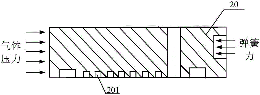
[0022] The outer peripheral surface of the static ring 9 is prov...


PUM


Abstract

The invention provides a static pressure gas labyrinth throttle regulating mechanism for both dynamic and static pressure dry gas seals, wherein a third radial air inlet and an axial throttle hole are both formed in a static sealing ring, the third radial air inlet is communicated with a labyrinth seal, and is located at a comb area of the labyrinth seal, the axial throttle hole is communicated with a pressure groove of a seal end surface, the other end is sealed tightly by countersunk bolts; the interior of the labyrinth seal is provided a second radial air inlet by processing, a static pressure gas cavity is formed among the outer circle of the labyrinth seal, an intrinsic pressure cover and a stationary seal ring, a first radial air inlet and a second radial air inlet are both connected with the static pressure gas cavity; the inner circle of the labyrinth seal is provided with two sealing rings, gases entering the labyrinth seal can only flow into the third radial throttle hole, a third sealing ring is arranged between the outer circle of the throttle hole and the intrinsic pressure cover, a first sealing ring is arranged between the static ring and the interior pressing cover; the labyrinth end nearing the exterior press cover is provided with a spring for a regulator. which drives the labyrinth seal to slide along the outer circle of the static ring, thereby achieving the gas static pressure regulating function through the third radial air inlet.

Description

(1) Technical field [0001] The invention relates to the structural design and application field of dynamic and static pressure dry gas seals, in particular to a static pressure gas labyrinth throttling control mechanism for dynamic and static pressure dry gas seals, especially suitable for rotating equipment under variable working conditions Shaft end seal. (2) Background technology [0002] Dry gas seal is a kind of rotary sealing device. Because of its characteristics of no liquid, low leakage, environmental protection, energy saving and long life, researchers try to use dry gas seal in more dynamic seals of rotating machines. However, through practice and theoretical analysis, it is found that the stability of the dry gas seal depends to a large extent not only on the dynamic balance performance of the rotor of the unit, but also on the minimum speed of the dry gas seal dynamic ring. The reason is that the dry gas seal requires non-contact operation with a small gap, and...

Claims


Application Information

Patent Timeline
Patent Type & Authority Patents(China)
IPC IPC(8): F16J15/40
CPCF16J15/40
Inventor 彭旭东赵艳凤江锦波孟祥铠陈源李纪云
Owner ZHEJIANG UNIV OF TECH
Why Eureka
Try Eureka