Underwater manifold connector

A connector and manifold technology, applied in flange connection, pipe/pipe joint/pipe fitting, fluid pressure actuating device, etc., can solve the problem of uneven force on the jaws, save material costs and improve service life and reliability and ease of installation

Active Publication Date: 2017-01-25
JIANGSU UNIV OF SCI & TECH
View PDF6 Cites 2 Cited by
  • Summary
  • Abstract
  • Description
  • Claims
  • Application Information

AI Technical Summary

Problems solved by technology

[0006] Purpose of the invention: In order to overcome the deficiencies in the prior art, the present invention provides an underwater manifold connector with a conical block on the manifold, with its own guiding and centering functions, which is easy to install and easy to disassemble and replace. The hydraulic drive ensures uniform distribution of the claws and avoids the defect of uneven stress on the claws due to fatigue wear of mechanical parts

Method used


Image

  • Underwater manifold connector
  • Underwater manifold connector
  • Underwater manifold connector

Examples


Embodiment Construction

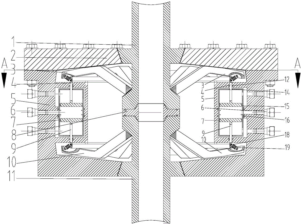
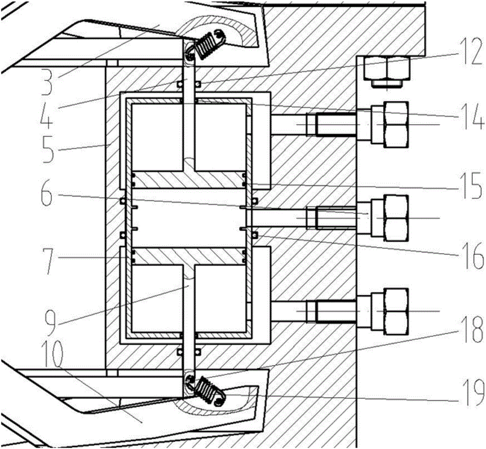
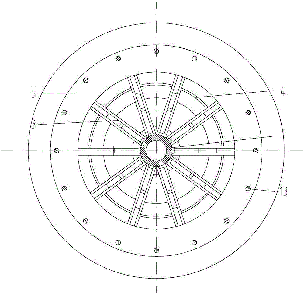
[0022] Such as Figure 1 to Figure 5 As shown, an underwater manifold connector of the present invention includes a base body 5, and a first cavity is provided in the base body 5, and the first cavity is connected to the connector end cover through 16 connecting bolts 13 2. Sealing. There is a floating hydraulic cylinder 7 in the first cavity. The floating hydraulic cylinder 7 is located in the second cavity extending from the base body 5. The second cavity is circular, and the liquid level of the floating hydraulic cylinder 7 is circular. , the floating hydraulic cylinder 7 is provided with several groups of upper piston rods 4 and lower piston rods 9, and the connecting pipe 1 and the connected pipe 11 to be connected are arranged in the base body 5, and the ends of the connecting pipe 1 and the connected pipe 11 The upper part of the conical boss and the lower conical boss are respectively provided, and a sealing ring is provided between the connecting pipe 1 and the connec...


PUM


Abstract

The invention discloses a underwater manifold connector which comprises a base body, wherein a first cavity is formed in the base body and sealed by an end cover of the connector, a floating hydraulic cylinder is arranged in the first cavity and located in a second cavity extended by the base body, an upper piston rod and a lower piston rod are arranged in the floating hydraulic cylinder, a connection pipe required for connection and a connected pipe are arranged in the base body, an upper conical boss and a lower conical boss are arranged at the end parts of the connection pipe and the connected pipe respectively, a sealing ring is arranged between the connection pipe and the connected pipe, a plurality of upper clamping jaws are circumferentially distributed on the upper conical boss, and a plurality of lower clamping jaws are circumferentially distributed on the lower conical boss. According to the underwater manifold connector, a conical block is arranged on a manifold and has guiding and alignment functions, the installation is convenient, disassembly and replacement are convenient, and the defect that the clamping jaws bear stress unuiformly due to fatigue wear of mechanical parts can be overcome while uniform distributing of the clamping jaws is ensured by hydraulic driving.

Description

technical field [0001] The invention relates to an underwater manifold connector and belongs to the field of underwater connectors. Background technique [0002] With the discovery of deep-sea oil and gas fields in recent years, the development of deep-sea equipment has been greatly promoted. The underwater manifold connector is one of the key components in deep-sea equipment. The stability of the device, and the thrust of the jaws on the seal should be evenly distributed on the premise of satisfying the uniform distribution in the circumferential direction. [0003] At present, there are two structures to ensure the uniform distribution of the jaw sealing force: [0004] (1) Positioning grooves are set on the back of the claws, and the circumferential uniform distribution of the claws is realized through the positioning pins set on the drive ring. The assembly process of this method is relatively simple, but it needs to open a long positioning groove on the back of the cl...

Claims


Application Information

Patent Timeline
Patent Type & Authority Applications(China)
IPC IPC(8): F16L23/024F16L23/18F15B15/14
CPCF15B15/1414F16L23/024F16L23/18
Inventor 朱永梅杭卫张建姚祥
Owner JIANGSU UNIV OF SCI & TECH
Why Eureka
Try Eureka