DLP projector automatic focusing mechanism and application thereof

An automatic focusing and projector technology, applied in the field of projection, can solve problems such as cost increase, deformation of printed items, eye damage, etc., and achieve the effect of avoiding damage

Inactive Publication Date: 2018-01-16
GUANGZHOU GUOGUANG INSTR
View PDF11 Cites 8 Cited by
  • Summary
  • Abstract
  • Description
  • Claims
  • Application Information

AI Technical Summary

Problems solved by technology

DLP technology can be used for 3D printing, but the existing DLP projection equipment is not specially developed for 3D printing, most of them have a projection elevation angle
If the DLP is simply fixed and installed, when adjusting the size of the projection surface, in order to make the projection surface centered on the resin tank, the only way to adjust the inclination angle of the DLP is to adjust the inclination angle of the DLP. Once the DLP projection light path is not perpendicular to the projection surface, the projected picture will tend to The trapezoidal shape will eventually lead to the deformation of the printed item; every time the projected image size is changed, the focus knob needs to be manually adjusted to make the projected image clear. Since a window needs to be reserved on the DLP projector for the user to view the focused image, the cost increases
Moreover, the ultraviolet DLP projector will project ultraviolet light with a wavelength of 405nm, which is easy to cause damage to human eyes, and this damage cannot be avoided when manual focus is used

Method used


Image

  • DLP projector automatic focusing mechanism and application thereof
  • DLP projector automatic focusing mechanism and application thereof
  • DLP projector automatic focusing mechanism and application thereof

Examples


Embodiment Construction

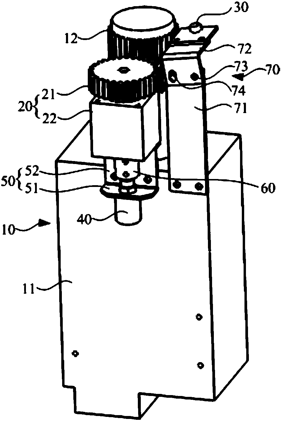
[0034] The technical solutions of the present invention will be further described below in conjunction with the accompanying drawings and through specific implementation methods.

[0035] In the description of the present invention, it should be understood that the orientation or positional relationship indicated by the terms "inner", "outer", etc. is based on the orientation or positional relationship shown in the drawings, and is only for the convenience of describing the present invention and simplifying the description. It is not intended to indicate or imply that the referred device or element must have a particular orientation, be constructed in a particular orientation, and operate in a particular orientation, and thus should not be construed as limiting the invention.

[0036] In addition, the terms "first" and "second" are used for descriptive purposes only, and cannot be interpreted as indicating or implying relative importance or implicitly specifying the quantity of...


PUM


Abstract

The invention discloses a DLP projector automatic focusing mechanism and an application thereof. The DLP projector automatic focusing mechanism comprises a DLP projector, a driving assembly and a camera connected with a main controller; the DLP projector comprises a projection body and a focusing rotary knob connected with the projection body; the driving assembly is connected with the focusing rotary knob for driving the focusing rotary knob to rotate; and the camera is arranged close to the focusing rotary knob for collecting a projection image of the DLP projector. According to the projector automatic focusing mechanism, the image collected by the camera is analyzed and processed through the main controller, and the image definition is judged; before the image definition satisfies requirement, the main controller automatically controls the driving assembly to drive the focusing rotary knob to rotate so as to realize automatic focusing of the DLP projector; compared with a manual focusing mode in the prior art, automatic focusing can be realized by the automatic focusing mechanism, without needing to reserve a window for allowing a user to check a focused image in the DLP projector; and in addition, harm of ultraviolet light from the DLP projector to human eyes can be avoided.

Description

technical field [0001] The invention relates to projection technology, in particular to an automatic focusing mechanism of a DLP projector used in a 3D printer and its application. Background technique [0002] As additive manufacturing technology matures, 3D printers are becoming more common. DLP technology can be used for 3D printing, but existing DLP projection devices are not specially developed for 3D printing, and most of them have a projection elevation angle. If the DLP is simply fixed and installed, when adjusting the size of the projection surface, in order to make the projection surface centered on the resin tank, the only way to adjust the inclination angle of the DLP is to adjust the inclination angle of the DLP. Once the DLP projection light path is not perpendicular to the projection surface, the projected picture will tend to The trapezoidal shape will eventually lead to deformation of the printed item; every time the projected image size is changed, the foc...

Claims


Application Information

Patent Timeline
Patent Type & Authority Applications(China)
IPC IPC(8): G03B21/53H04N9/31
Inventor 林贵棱陈立鹏辛荣
Owner GUANGZHOU GUOGUANG INSTR
Why Eureka
Try Eureka