
Backlight module and display device

A backlight module and display device technology, applied in light guides, optics, optical components, etc., can solve problems such as light leakage, poor display quality, and reduced competitiveness, and achieve the effect of improving the coupling effect

Inactive Publication Date: 2017-01-25
HANNSTAR DISPLAY NANJING +1
View PDF4 Cites 2 Cited by
  • Summary
  • Abstract
  • Description
  • Claims
  • Application Information

AI Technical Summary

Problems solved by technology

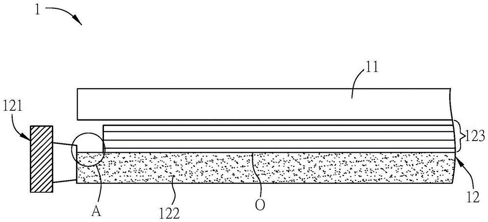
[0005] However, in the known technology, such as figure 1 As shown, since the light guide plate 122 is generally made of a light-transmitting material, the light that enters the light guide plate 122 from the light incident surface 1 will directly enter the inside of the light guide plate 122, so that the area adjacent to the light guide plate 122 and the LED light source 121 (such as figure 1 In the region A), light leakage often occurs, causing hot spots on the display panel 11, resulting in poor display quality and a decline in product competitiveness.

Method used


Image

  • Backlight module and display device
  • Backlight module and display device
  • Backlight module and display device

Examples


Embodiment Construction

[0019] A backlight module and a display device according to preferred embodiments of the present invention will be described below with reference to related drawings, wherein the same components will be described with the same reference numerals.

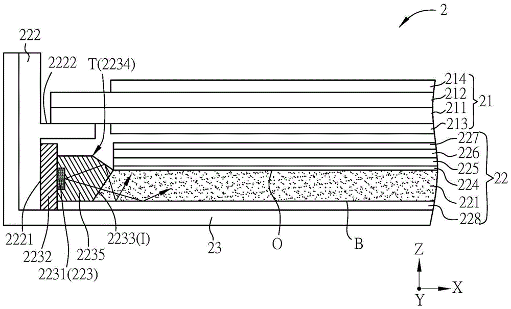
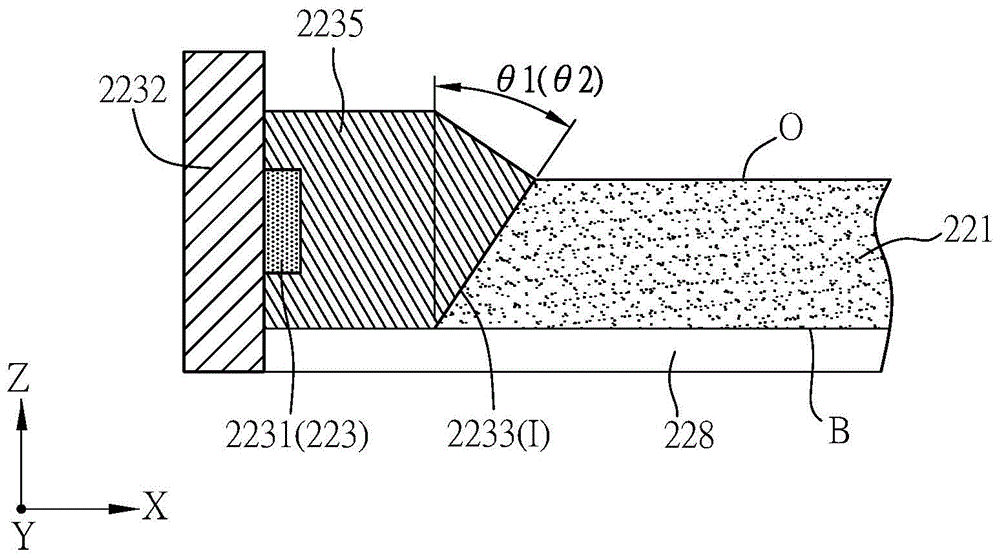
[0020] Please refer to Figure 2A and Figure 2B As shown, among them, Figure 2A is a schematic diagram of a display device 2 in a preferred embodiment of the present invention, and Figure 2B for Figure 2A A partially enlarged schematic diagram. In this embodiment, the first direction X (horizontal direction), the second direction Y and the third direction Z (vertical direction) are shown, and the first direction X, the second direction Y and the third direction Z are substantially perpendicular to each other. . Wherein, the first direction X may be substantially parallel to the extending direction of the scanning lines of the display device 2, the second direction Y may be substantially parallel to the extending direction o...


PUM


Abstract

The invention provides a backlight module and a display device; the backlight module comprises a light guide plate and a light-emitting unit; the light guide plate has at least one incident side and an emergent side connected with the incident side; the light-emitting unit has a substrate, at least one light-emitting device and a light exiting side, the light-emitting devices are disposed on the substrate, and light source is provided for the light-emitting devices by the light exiting side and enters the light guide plate from the incident side out of the light exiting side, wherein the incident side has a first inclination angle to a direction perpendicular to the light exiting side, the light exiting side has a second inclination angle to the direction, and the first inclination angle and the second inclination angle are identical in nature.

Description

technical field [0001] The invention relates to a backlight module and a display device. Background technique [0002] Since the display medium of the liquid crystal display panel does not emit light, in order to achieve the display effect, it is necessary to provide a surface light source (that is, a backlight module) with sufficient brightness and uniform distribution to the liquid crystal display panel to display the desired image. In addition, due to continuous improvements in technology and materials of light emitting diodes (Light Emitting Diodes, LEDs), the luminous efficiency of light emitting diodes has been greatly improved. Due to the characteristics of low power consumption, long service life, high safety, short light-emitting response time and small size, light-emitting diodes are gradually applied in backlight modules of display devices. [0003] Please refer to figure 1 As shown, it is a schematic diagram of a known display device 1 . [0004] The display d...

Claims


Application Information

Patent Timeline
Patent Type & Authority Applications(China)
IPC IPC(8): G02B6/00G02F1/13357
CPCG02B6/0013G02F1/133606
Inventor 林进伟苏材龙古伟明钟明宏
Owner HANNSTAR DISPLAY NANJING
Learn More