
A method for hot dismantling of motor windings

A technology of motor windings and windings, which is used in electric components, manufacturing motor generators, electromechanical devices, etc., can solve problems such as large viscous force and motor scrapping.

Active Publication Date: 2019-08-06
邢义军
View PDF1 Cites 0 Cited by
  • Summary
  • Abstract
  • Description
  • Claims
  • Application Information

AI Technical Summary

Problems solved by technology

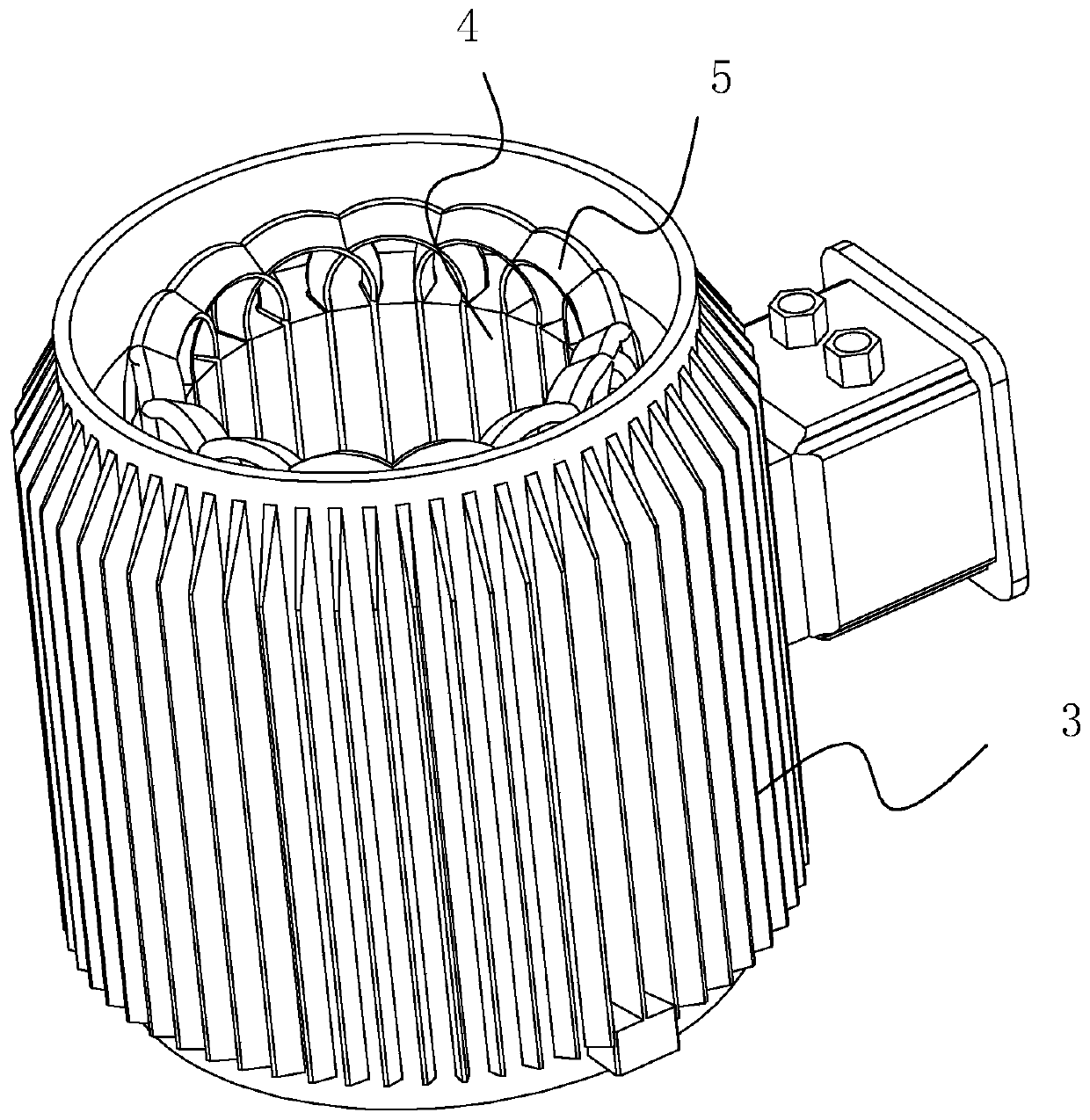
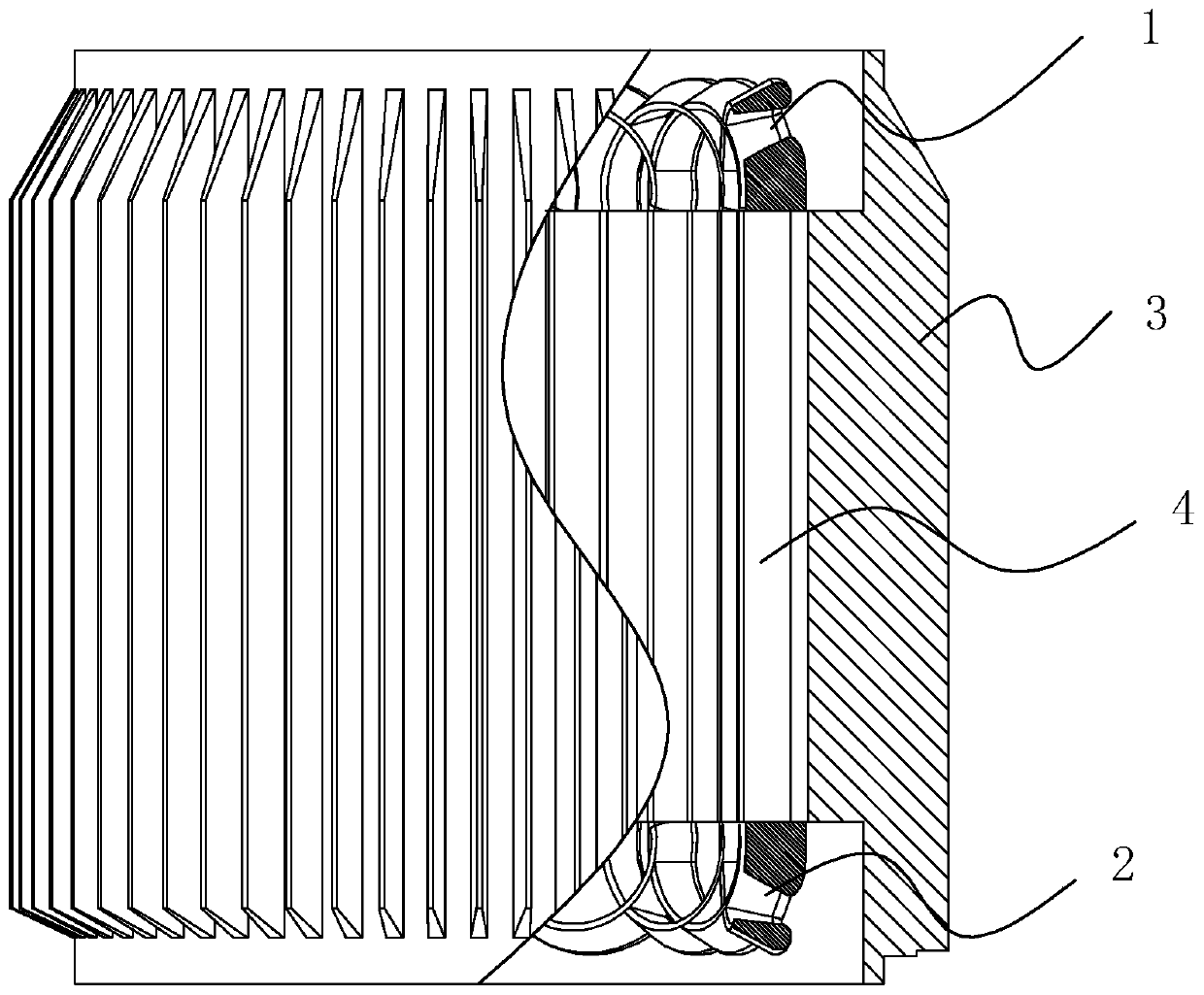
[0004] For the motor with the above structure, the motor maintenance industry usually adopts the cold dismantling method, the so-called cold dismantling method, that is, first cut off the upper winding 1 or the lower winding 2, and then use the tension mechanism to clean the lower winding 1 or the lower winding at the other end. 2 Apply tension, and the entire coil winding 5 can be disassembled from the silicon steel sheet group 4; although the cold disassembly method is quick to disassemble, there is a very fatal shortcoming, that is, there is insulation between the coil winding 5 and the silicon steel sheet group 4 paper, and the outer wall of the coil winding 5 is coated with insulating varnish, resulting in a relatively large viscous force between the coil winding 5 and the silicon steel sheet group 4. When the coil winding 5 is pulled, the coil winding 5 will contact the silicon steel sheet There will be a huge pulling force between the groups 4, which may cause the silicon steel sheet group 4 to separate from the fixed casing, or directly cause the silicon steel sheets in the silicon steel sheet group 4 to separate from each other, causing the motor to be scrapped

Method used


Image

  • A method for hot dismantling of motor windings
  • A method for hot dismantling of motor windings

Examples


Embodiment Construction

[0036] In order to make the purpose, technical solution and advantages of the present invention clearer, a method for hot dismantling of motor windings according to the present invention will be further clearly and completely described below with reference to the accompanying drawings. Apparently, the described embodiments are some, but not all, embodiments of the present invention. Based on the described embodiments of the present invention, all other embodiments obtained by persons of ordinary skill in the art without creative efforts shall fall within the protection scope of the present invention.

[0037] attached figure 1 and attached figure 2 Both are schematic diagrams of the internal structure of the existing motor stator, and will not be described in detail in this manual.

[0038] A method for hot dismantling of motor windings, comprising the following steps:

[0039] Step1, tangent: Use a shovel or a cutting tool to cut the upper winding 1 or the lower winding 2...


PUM


Abstract

The invention discloses a hot disassembling method of a motor winding. According to a key point of the technical scheme, the hot disassembling method comprises the following steps: step 1: cutting, namely cutting an upper winding or a lower winding of a coil winding by using a scraper knife or a cutting tool, and completely cutting off one of the upper winding or the lower winding from the coil winding; step 2: heating, namely heating a fixed shell in the step 1; step 3: unplugging, namely when the upper winding is cut off, pulling the lower winding by using an external tool, so as to completely separate the coil winding from a silicon steel sheet group; or when the lower winding is cut off, pulling the upper winding by using the external tool, so as to completely separate the coil winding from the coil winding; step 4: removing insulation paper, namely removing insulation paper adhered in the silicon steel sheet group; and step 5: removing insulation paint, namely removing insulation paint adhered at the outer side of the silicon steel sheet, wherein the operation sequence of the step 4 and step 5 can be changed. The hot disassembling method of the motor winding is smooth in disassembling process. The motor is smooth in disassembling process and extremely low in scrap rate.

Description

technical field [0001] The invention relates to a method for dismantling a motor coil, more specifically, it relates to a method for hot dismantling a motor winding. Background technique [0002] The motor is widely used in the industrial field, and its structure is relatively simple. The existing motor structure mainly includes a stator and a rotor. The rotor is located inside the stator and can rotate around the rotor. [0003] The stator structure is as attached figure 1 and attached figure 2 As shown, it includes a fixed casing 3, and the fixed casing 3 is provided with a silicon steel sheet group 4, and the silicon steel sheet group 4 is internally wound with a coil winding 5, and between the silicon steel sheet group 4 and the fixed casing 3 After fastening, firstly, in order to prevent direct contact between the coil winding 5 and the silicon steel sheet group 4, insulating paper will be placed between the two; secondly, in order to increase the high temperature re...

Claims


Application Information

Patent Timeline
Patent Type & Authority Patents(China)
IPC IPC(8): H02K15/00
CPCH02K15/0006
Inventor 邢义军
Owner 邢义军
Learn More