Engine assisted brake control on wheel slip

An engine and wheel technology, applied in the direction of brakes, control devices, etc., can solve problems such as mechanical wear, weight increase, damage, etc.

Inactive Publication Date: 2017-01-25
CATERPILLAR INC
View PDF1 Cites 3 Cited by
  • Summary
  • Abstract
  • Description
  • Claims
  • Application Information

AI Technical Summary

Problems solved by technology

However, the choice is not entirely ideal
Differential locks, for example, require additional equipment to be added to the machine in question

Method used


Image

  • Engine assisted brake control on wheel slip
  • Engine assisted brake control on wheel slip
  • Engine assisted brake control on wheel slip

Examples


Embodiment Construction

[0011] It should be noted that the methods and systems described herein can be adapted to a variety of machines. The machine may be an off-highway vehicle, such as a truck, used in operations in connection with industries such as mining, construction, agriculture, transportation or any other industry known in the art. For example, the machine may be an off-highway truck or an earth moving machine such as a bulldozer, wheel loader, excavator, dump truck, backhoe, motor grader, material handler, and the like.

[0012] Furthermore, it should be noted that the drawings are merely illustrative and not drawn to scale.

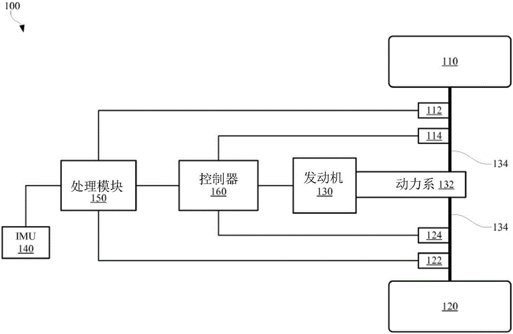
[0013] figure 1 is a schematic diagram of a portion of an exemplary machine 100 in accordance with at least one embodiment of the invention. Some example machines 100 may include a chassis and wheels 110, 120 (or tracks). In some examples, machine 100 may have multiple wheels, such as four or six wheels. For exemplary purposes, figure 1 Only two wheels 110, 120 ...


PUM


Abstract

Wheel (110) slippage of a machine (100) may be controlled using brake (114) control and engine (130) torque control. In some examples, the present disclosure describes a method of controlling a wheel (110). Example methods may include sensing a rotational speed of the wheel (110), and sensing an acceleration of the machine (100). The method may also include estimating a target speed (212) of the wheel (110) based at least in part on the rotational speed of the wheel (110) and the acceleration of the machine (100). The method may continue with calculating a speed error, the speed error being a difference between the rotational speed and the target speed. The method may also include controlling a brake (114) of the wheel (110) based on the speed error and/or a torque of an engine (130) of the machine (100) based on the speed error.

Description

technical field [0001] The present patent disclosure generally relates to controlling wheel slip of a machine based on wheel speed and machine state via brake control and engine control. Background technique [0002] Wheel slip occurs during operation of many machines, including off-highway vehicles. Such wheel slip occurs due to various factors, including wheel type, surface type, and environmental conditions. Conventional methods of limiting wheel slip (or traction control) such as brake control for off-highway vehicles, while available, are not sufficient. [0003] Among other approaches, such as in U.S. Patent No. 7,856,303 entitled "Method for Determining Wheel Slip and Engaging Differential Lock in a Work Vehicle," there is a need for a differential lock for reducing wheel slip shift. In these cases, the differential automatically locks when a wheel slip condition is sensed. However, this option is not entirely ideal. For example, differential locks require additi...

Claims


Application Information

Patent Timeline
IPC IPC(8): B60T8/1761
CPCB60T8/175B60W10/06B60W10/184B60W30/18172B60W2050/0011B60W2520/105B60W2520/16B60W2520/28B60W2710/0666B60W2720/28B60T8/245B60T8/3205B60T8/58
Inventor Y·刘G·麦卡恩S·伍尔夫R·惠廷顿
Owner CATERPILLAR INC
Why Eureka
Try Eureka