Crawler type water removal device used for tire rubber assembly

A crawler and rubber technology, which is applied in the field of rubber tire production, can solve the problems of small contact area, low water absorption efficiency, and inability to absorb water cleanly, so as to prolong the service life and save energy

Active Publication Date: 2017-02-01
山东新大陆橡胶科技有限公司
View PDF6 Cites 4 Cited by
  • Summary
  • Abstract
  • Description
  • Claims
  • Application Information

AI Technical Summary

Problems solved by technology

Compared with patent ZL201120555189.2, the patent ZL201020169996.6 increases the contact area between the sponge and the rubber component, but it is still a line contact, and the contact area is still small; there is also no relative displacement between the contact surface of the sponge and the rubber component, and the water absorption The efficiency is not high; the water in the sponge roller is not squeezed out, and after a long time of operation, the water on the upper surface of rubber components such as treads and sidewalls cannot be completely absorbed

Method used


Image

  • Crawler type water removal device used for tire rubber assembly
  • Crawler type water removal device used for tire rubber assembly
  • Crawler type water removal device used for tire rubber assembly

Examples


Embodiment 1

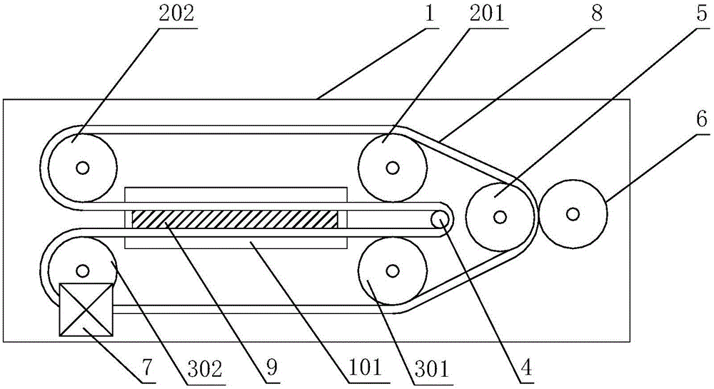
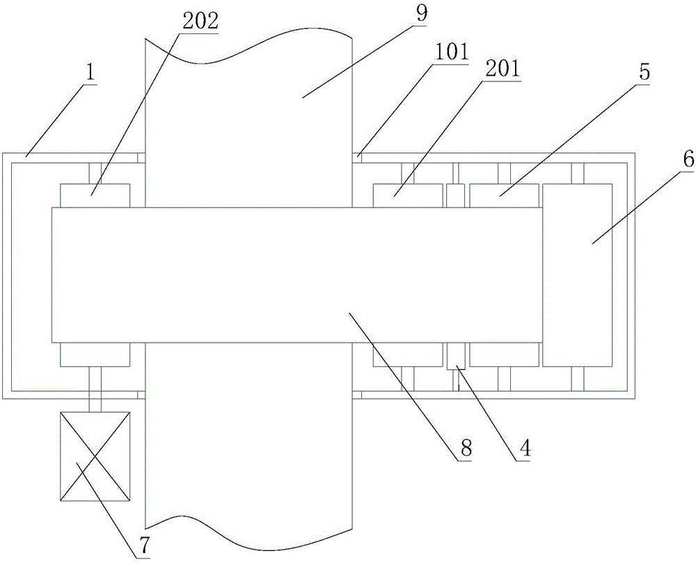
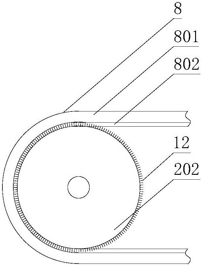
[0037]The crawler-type dewatering device for tire rubber components involved in this embodiment has a main structure including a frame 1, an upper head support roller 201, an upper tail support roller 202, a lower head support roller 301, a lower tail support roller 302, an internal variable Toward roller 4, outward changing roller 5, squeezing roller 6, driving device 7 and crawler-shaped sponge 8; material channel 101 is reserved on frame 1; upper head support roller 201, upper tail support roller 202, lower head support roller 301 , the lower tail supporting roller 302, the inner turning roller 4, the outer turning roller 5, the squeezing roller 6 and the driving device 7 are respectively fixedly installed on the frame 1; the upper supporting roller 201, the upper tail supporting roller 202, the lower supporting roller The axes of the roller 301, the lower tail support roller 302, the inner reversing roller 4, the outer reversing roller 5 and the squeeze roller 6 are paralle...

Embodiment 2

[0053] Such as Figure 4 As shown, the crawler-type dewatering device for tire rubber components involved in this embodiment has the same main structure as that of Embodiment 1, except that an upper middle support roller 201 and an upper tail support roller 202 are provided between The support roller 203; the lower middle support roller 303 is arranged between the lower head support roller 301 and the lower tail support roller 302.

Embodiment 3

[0055] Such as Figure 5 , Figure 6 As shown, the crawler-type water removal device for tire rubber components involved in this embodiment has the same main structure as that of Embodiment 1, except that it also includes a water receiving tank 10, which is located between the outer direction changing roller 5 and the Below the water squeeze roller 6 gaps; the water receiving tank 10 is shaped as a strip-shaped long groove, the long side of the water receiving tank 10 is parallel to the axis of the water squeezing roller 6, and the length of the long side of the water receiving tank 10 is greater than the width of the track-shaped sponge 8, Water receiving tank 10 bottom is connected with drainage pipe 11;


PUM


Abstract

The invention relates to a crawler type water removal device used for a tire rubber assembly. The crawler type water removal device comprises a rack, an upper head supporting roller, an upper tail supporting roller, a lower head supporting roller, a lower tail supporting roller, an inner turning roller, an outer turning roller, a water extrusion roller, a drive device and a crawler sponge; the upper supporting rollers, the inner turning roller, the lower supporting rollers and the outer turning roller are sequentially sleeved with the crawler sponge, and the moving direction of the crawler sponge is perpendicular to the moving direction of the tire rubber assembly; the device makes friction with the upper surface and the lower surface of the tire rubber assembly through the crawler sponge, meanwhile, water on the upper surface and the lower surface of the tire rubber assembly can be dried, energy is saved, and the environment-friendly effect is achieved; a cord layer can prolong the service life of the crawler sponge, and on the premise of protecting the crawler sponge against damage, the rubber assembly can smoothly penetrate the crawler sponge.

Description

[0001] Technical field: [0002] The invention belongs to the technical field of rubber tire production, and in particular relates to a crawler-type dewatering device for tire rubber components, which efficiently and cleanly wipes off the moisture on the surface of the rubber components by friction between the sponge and the upper and lower surfaces of the tire rubber components . [0003] Background technique: [0004] In the production process of existing tires, due to the high temperature of rubber components such as sidewalls and treads after being extruded from the machine head, cooling is required. Most tire manufacturers use water cooling to cool down, and rubber components such as sidewalls and treads pass through After spraying and cooling, water droplets and water stains will adhere to the upper and lower surfaces. Due to process requirements, there must be no moisture on the surface of the various components when they are laminated and assembled, otherwise it will a...

Claims


Application Information

Patent Timeline
Patent Type & Authority Applications(China)
IPC IPC(8): B08B1/02B29C47/08B29D30/16B29D30/30
CPCB08B1/006B08B1/02B29C48/274B29D30/16B29D30/30B29D2030/1664B29D2030/3064
Inventor 王金山刘奇王成杰
Owner 山东新大陆橡胶科技有限公司
Why Eureka
Try Eureka