Automatic pull device for cable cutting

A traction device and automatic technology, applied in the field of traction devices, can solve the problems of low cable traction efficiency, low degree of automation, and labor and material resources consumption, and achieve the effects of simple and efficient device layout, improved automation, and low loss

Inactive Publication Date: 2017-02-01
GANZHOU JINXINNUO CABLE TECH
View PDF10 Cites 8 Cited by
  • Summary
  • Abstract
  • Description
  • Claims
  • Application Information

AI Technical Summary

Problems solved by technology

[0006] In order to overcome the disadvantages of low automation, manpower and material resources in the cable traction process under the existing technical conditions, resulting in low cable traction efficiency and easy damage to the cable, the technical problem to be solved by the present invention is to provide a Automatic pulling device for cable cutting with high efficiency and high cable pulling efficiency, which is not easy to damage the cable

Method used


Image

  • Automatic pull device for cable cutting
  • Automatic pull device for cable cutting
  • Automatic pull device for cable cutting

Examples


Embodiment 1

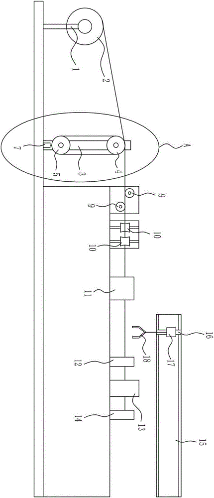
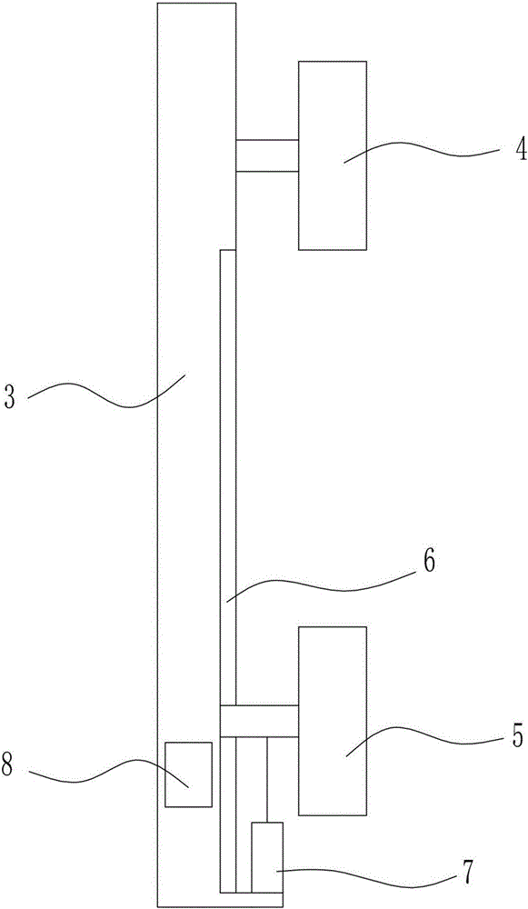
[0021] An automatic pulling device for cable cutting, such as Figure 1-Figure 2 As shown, it includes a pay-off stand 1, a bracket 3, an upper winding wheel 4, a lower winding wheel 5, a cylinder 7, a tension sensor 8, a horizontal guide wheel 9, a vertical guide wheel 10, a wire sheath 11, a clip Thread controller I12, thread gripper II14, pneumatic cutter 13, horizontal guide rail 15, vertical guide rail 16, guide block 17 and manipulator 18, the right side of pay-off frame 1 is provided with support 3, and the upper part of support 3 is rotatably provided with an upper winding Wire wheel 4, support 3 bottom is provided with chute 6, and lower winding wheel 5 is installed in chute 6, is connected with cylinder 7 on the lower winding wheel 5, and the other end of cylinder 7 is installed on the support 3, and lower winding wheel 5. The rear side is provided with a tension sensor 8, the right side of the support 3 is provided with a horizontal guide wheel 9, the right side of ...

Embodiment 2

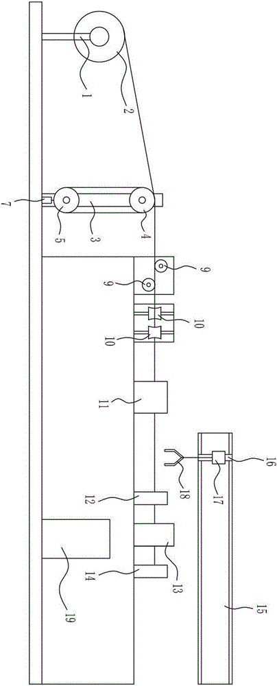
[0023] An automatic pulling device for cable cutting, such as Figure 1-Figure 3 As shown, it includes a pay-off stand 1, a bracket 3, an upper winding wheel 4, a lower winding wheel 5, a cylinder 7, a tension sensor 8, a horizontal guide wheel 9, a vertical guide wheel 10, a wire sheath 11, a clip Thread controller I12, thread gripper II14, pneumatic cutter 13, horizontal guide rail 15, vertical guide rail 16, guide block 17 and manipulator 18, the right side of pay-off frame 1 is provided with support 3, and the upper part of support 3 is rotatably provided with an upper winding Wire wheel 4, support 3 bottom is provided with chute 6, and lower winding wheel 5 is installed in chute 6, is connected with cylinder 7 on the lower winding wheel 5, and the other end of cylinder 7 is installed on the support 3, and lower winding wheel 5. The rear side is provided with a tension sensor 8, the right side of the support 3 is provided with a horizontal guide wheel 9, the right side of ...


PUM


Abstract

The invention relates to a pull device, in particular to an automatic pull device for cable cutting. In order to achieve the technical aims, the automatic pull device for cable cutting is high in automation degree and cable pull efficiency, and cables are not prone to being damaged. The device comprises a pay-off rack, a support, an upper reel, a lower reel, an air cylinder, a tension inductor and the like. The support is arranged on the right side of the pay-off rack. The upper reel is rotationally arranged on the upper portion of the support. A sliding groove is formed in the lower portion of the support. The lower reel is mounted in the sliding groove. The air cylinder is connected to the lower reel. The other end of the air cylinder is mounted on the support. The tension inductor is arranged on the rear side of the lower reel. The automatic pull device overcomes the defects that under the existing technical conditions, in the cable pull process, the automation degree is low, time and labor are consumed, the cable pull efficiency is low, and cables are prone to being damaged; and the automatic pull device achieves the effects that the automation degree and the cable pull efficiency are high, and the cables are not prone to being damaged.

Description

technical field [0001] The invention relates to a pulling device, in particular to an automatic pulling device for cable cutting. Background technique [0002] With the development of science and technology, cables occupy an increasingly important position in production and life. Cables have many uses, mainly for multiple functions such as control installation, connection equipment, and power transmission. Cables are used in all aspects of production and life, and in the processing and production of cables, cable pulling is an indispensable step, but in this process, there are many problems that need to be solved urgently. During the pulling process of the cables, a lot of manpower and material resources are required, and irreparable damage is often caused due to excessive tension between the cables, resulting in unnecessary waste. [0003] During the cable pulling process, the damage to the quality of any part or process part of the cable is almost irreparable and irrepara...

Claims


Application Information

Patent Timeline
Patent Type & Authority Applications(China)
IPC IPC(8): B21F23/00B21F11/00
CPCB21F23/00B21F11/00
Inventor 桂宏兵梅春风汪传灯
Owner GANZHOU JINXINNUO CABLE TECH
Why Eureka
Try Eureka