Drum flying shears

A technology of flying shears and rollers, which is applied in the field of steel rolling machinery, can solve the problems of large shear impact force of thick materials, and achieve the effects of small shear impact force, reduced instantaneous impact force, and large system inertia

Active Publication Date: 2017-02-01
CERI TECH +1
View PDF6 Cites 3 Cited by
  • Summary
  • Abstract
  • Description
  • Claims
  • Application Information

AI Technical Summary

Problems solved by technology

[0008] The purpose of the present invention is to provide a drum flying shear that can meet the shearing accuracy requirements of flying shears for thin materials and at the same time solve the problem of large shearing impact force of thick materials

Method used


Image

  • Drum flying shears
  • Drum flying shears
  • Drum flying shears

Examples


Embodiment Construction

[0040] In order to have a clearer understanding of the technical solutions, objectives and effects of the present invention, the specific implementation manners of the present invention will now be described with reference to the accompanying drawings.

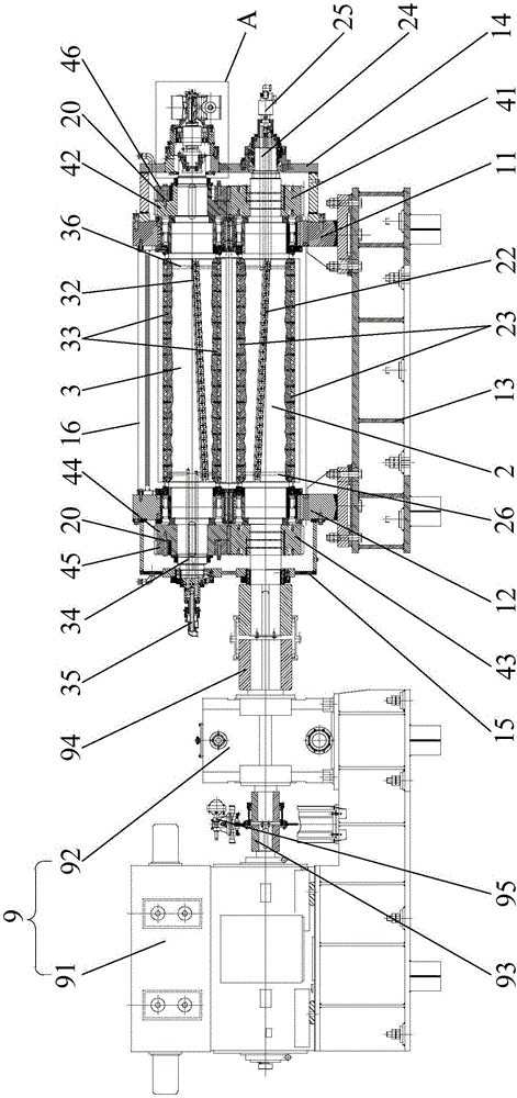
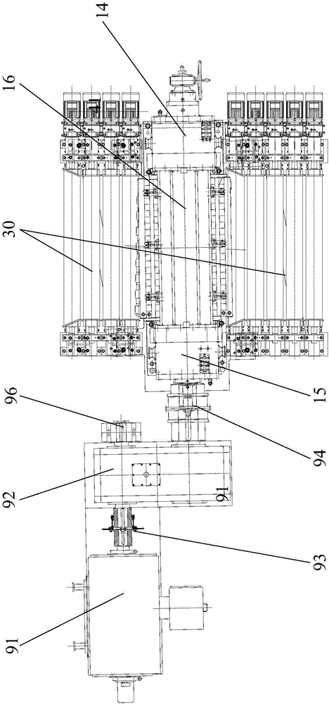
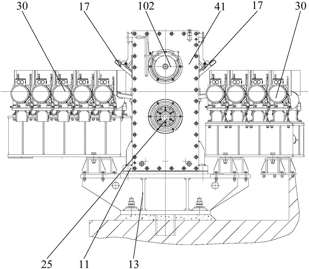
[0041] Such as figure 1 As shown, the present invention provides a drum flying shear, which includes: a frame 1 and a drive mechanism 9, wherein the upper part of the frame 1 is rotatably connected with parallel and spaced stacked driving knife shafts 2 and driven knives Axis 3, driving knife shaft 2 and driven knife shaft 3 are equal in diameter and connected by a transmission mechanism, which can drive the driven knife shaft 3 and the driving knife shaft 2 to rotate in reverse synchronously, as Figure 4 and Figure 5 As shown, the outer surface of the active cutter shaft 2 is provided with a linear first sipe 21 and a cylindrical helical second sipe 22 at intervals along the axial direction, that is, the first sipe 21 and ...


PUM


Abstract

The invention provides drum flying shears. The drum flying shears comprise a rack, wherein the upper part of the rack is rotationally connected with a driving cutter shaft and a driven cutter shaft which are parallel and overlaid in a spaced manner, the driving cutter shaft and the driven cutter shaft have equal diameter and are connected through a transmission mechanism, a linear first cutter groove and a cylindrical-helix-shaped second cutter groove are formed in a spaced manner in the outer surface of the driving cutter shaft in the axial direction, a linear third cutter groove and a cylindrical-helix-shaped fourth cutter groove are formed in a spaced manner in the outer surface of the driven cutter shaft in the axial direction, the fourth cutter groove and the second cutter groove have identical helix angle and opposite rotating directions, and shear blades are arranged in the first cutter groove, the second cutter groove, the third cutter groove and the fourth cutter groove respectively; a drive mechanism is connected with the driving cutter shaft and drives the driving cutter shaft to rotate, and the driving cutter shaft drives the driven cutter shaft through the transmission mechanism to rotate synchronously in the opposite direction. According to the provided drum flying shears, thick and thin strips with large thickness change ranges are sheared, the shearing precision is guaranteed, and the shearing impact is reduced.

Description

technical field [0001] The invention relates to the technical field of steel rolling machinery, in particular to a drum flying shear. Background technique [0002] At present, the flying shear equipment used in the production of plate and strip in the market mainly includes: [0003] (1) Use drum-type flying shears for the production of thin plates (the thickness of the strip is about 0.1mm-0.6mm). This kind of flying shears is mostly used in the post-processing line of cold rolling. The shearing speed is relatively low and the yield strength of the strip is not high. ; [0004] (2) Flying shears used for coiling after continuous cold rolling. The shearing speed of this flying shear is higher than that of the flying shearing equipment on the processing line. The sheared strip is cold-rolled due to the Work hardening, the yield stress is very high, and the thickness specification is generally 0.18mm-2.5mm; [0005] (3) Flying shears used in the hot rolling production line ...

Claims


Application Information

Patent Timeline
Patent Type & Authority Applications(China)
IPC IPC(8): B23D25/02
CPCB23D25/02
Inventor 常铁柱韩志勇胡晓军王蕾周西康张海东
Owner CERI TECH
Why Eureka
Try Eureka