
Suspension cushion

A technology for mounting soft pads and soft pads, which is applied in power units, jet propulsion units, internal combustion propulsion units, etc., can solve the problems affecting the noise level of the cab, the rise of the mount stiffness curve, and the shaking of the powertrain. Improve NVH performance, avoid sharp rise, smooth stiffness curve effect

Active Publication Date: 2017-02-01
ANHUI JIANGHUAI AUTOMOBILE GRP CORP LTD
View PDF11 Cites 1 Cited by
  • Summary
  • Abstract
  • Description
  • Claims
  • Application Information

AI Technical Summary

Problems solved by technology

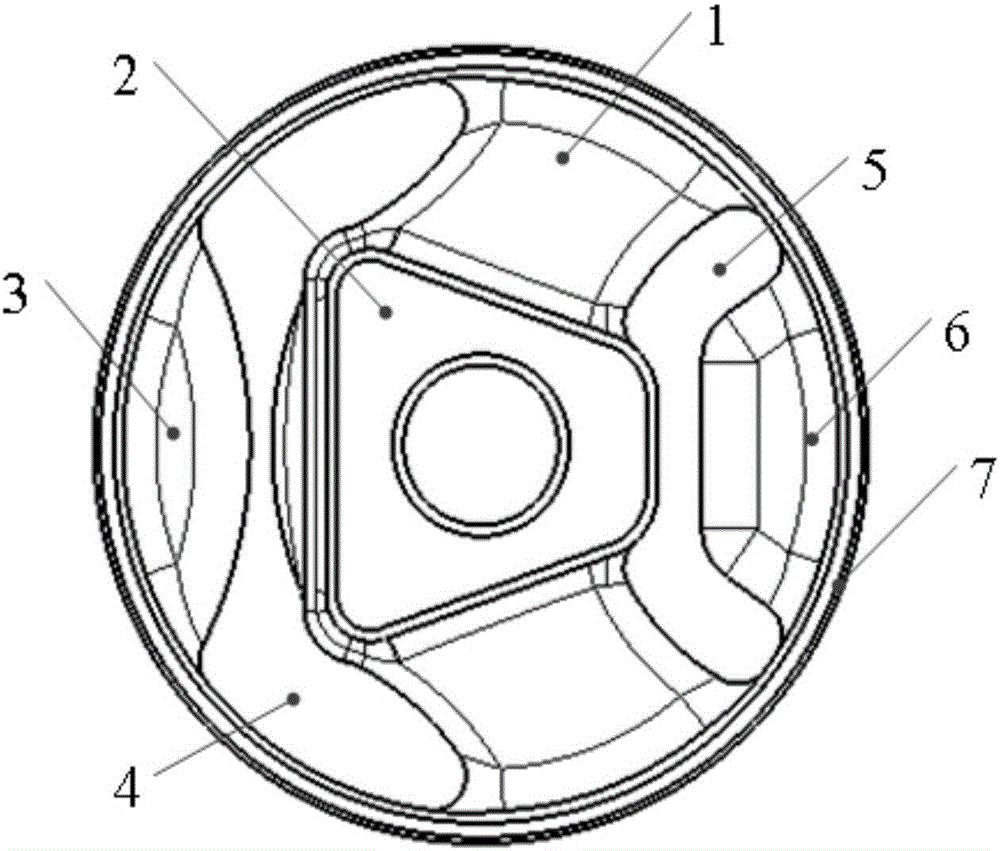
In the prior art, the size of the rubber body 1 in the working direction is too small, which is not conducive to NVH performance adjustment;
[0007] 2. The limit structure of the rubber bush 7 is limited by the contact between the rubbers, and there is no hard limit point, which is not conducive to controlling the displacement of the powertrain under severe working conditions;
[0008] 3. Since there is no hard limit point, the displacement of the powertrain cannot be effectively limited. Under severe working conditions, the powertrain will shake and cause the whole vehicle to shake;
[0009] 4. The jitter will generate noise and affect the noise level in the cab;
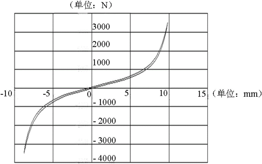
[0010] 5. Due to the large contact area between the rubber body 1 and the limit rubber, the suspension stiffness curve will rise sharply (see figure 2 The stiffness curve of the suspension cushion of the prior art shown) affects the vehicle NVH performance

Method used


Image

  • Suspension cushion
  • Suspension cushion
  • Suspension cushion

Examples


Embodiment Construction

[0044] Embodiments of the present invention are described in detail below, examples of which are shown in the drawings, wherein the same or similar reference numerals designate the same or similar elements or elements having the same or similar functions throughout. The embodiments described below by referring to the figures are exemplary only for explaining the present invention and should not be construed as limiting the present invention.

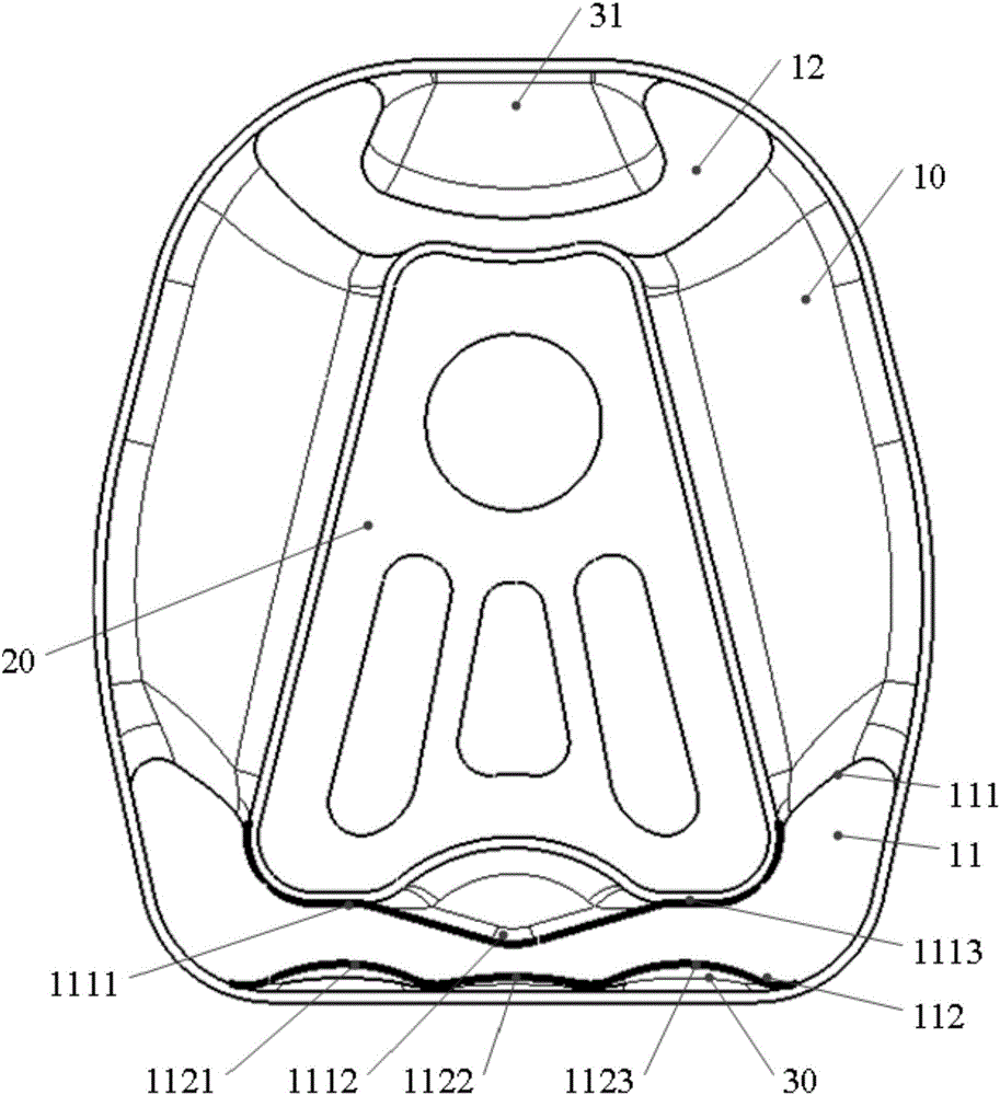
[0045] image 3 A schematic structural view of the suspension cushion provided by the embodiment of the present invention, such as image 3 As shown, the suspension cushion provided by the embodiment of the present invention includes a cushion body 10 and a suspension bracket 20 .

[0046] The cushion body 10 is symmetrically provided with a first cavity 11 and a second cavity 12 passing through the cushion body, the first cavity 11 is in the shape of a "concave", the second cavity 12 is a "trapezoid", and the "trapezoid" The bottom of...


PUM


Abstract

The invention discloses a suspension cushion which comprises a cushion body and a suspension support. A first cavity and a second cavity which penetrate the cushion body are symmetrically formed in the cushion body, the first cavity is in a concave shape, the second cavity is trapezoidal, the bottom of the trapezoidal shape is in an arc shape, the suspension support penetrates the cushion body between the first cavity and the second cavity, a first limiting cushion is arranged between the first cavity and the cushion body, and a second limiting cushion is arranged between the second cavity and the cushion body. In the suspension cushion, the upper end of the concave shape is in a straight line shape, the upper end of the trapezoidal shape is in a shape of being shrinking upwards while two cavities in the prior art are in an inverted V shape and the inverted V shape is open outwards; therefore, the contact area between the first limiting cushion and the cushion body is obviously reduced, the contact area between the second limiting cushion and the cushion body is also reduced, it is guaranteed that a rigidity curve of an automobile suspension system is stable, rapid rising of the rigidity curve is avoided, and thus the noise vibration and harshness (NVH) performance of the finished automobile is improved.

Description

technical field [0001] The invention relates to the technical field of automobile suspension systems, in particular to a suspension cushion. Background technique [0002] The research on the vibration isolation of the automobile powertrain mount system and the research on the engine intake and exhaust noise is an important content to improve the comfort of the whole vehicle. The development and improvement of the powertrain mount system can better solve this problem. The transmission and response of the suspension system to the excitation of road roughness has a great impact on the ride comfort of the driver and passengers. As a key component connecting the powertrain and the body, the performance of the suspension system will directly affect the NVH performance of the vehicle. Therefore, how to avoid the unreasonable design of the mounting system, or how to optimize the structure of the mounting system to improve its NVH performance has become the top priority of the mounti...

Claims


Application Information

Patent Timeline
Patent Type & Authority Applications(China)
IPC IPC(8): B60K5/12F16F15/08
CPCB60K5/1208F16F15/08
Inventor 李龙晶廖武张永康梁林苗文杰
Owner ANHUI JIANGHUAI AUTOMOBILE GRP CORP LTD
Learn More