Clamping head device of winding machine

A technology of winding machine and chuck, applied in the direction of winding strip, transportation and packaging, transportation of filamentous materials, etc. Good and other problems, to achieve the effect of simple structure, practical function, safe and convenient clamping

Inactive Publication Date: 2017-02-01
WUXI CHUANGHENG MACHINERY
View PDF7 Cites 6 Cited by
  • Summary
  • Abstract
  • Description
  • Claims
  • Application Information

AI Technical Summary

Problems solved by technology

[0002] In the machinery manufacturing industry, positioning and clamping are required in many large-scale mechanical structures to meet certain mechanical movements. In the prior art, the chuck structure of many clamping devices is complicated, the quality of customized processing is difficult to guarantee, and the cost is greatly increased. The processing method is inefficient, which greatly wastes human resources, and in many practical situations, the clamping effect is not good, and it cannot meet the production needs well.

Method used


Image

  • Clamping head device of winding machine

Examples


Embodiment Construction

[0012] Below the present invention will be further described in conjunction with the embodiment in the accompanying drawing:

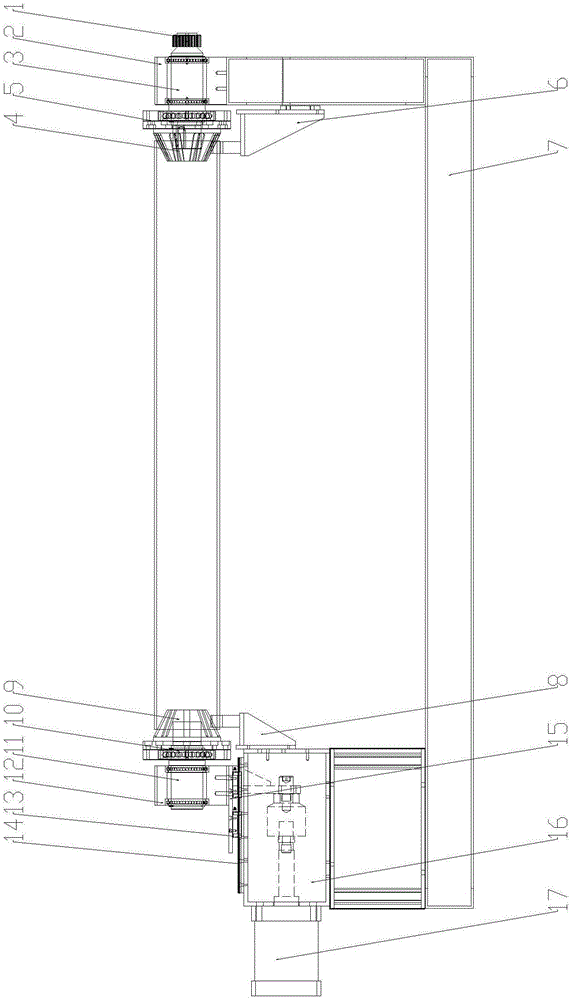
[0013] Such as figure 1 As shown, the present invention mainly includes a power end chuck assembly, a cylinder end chuck assembly, a push cylinder 17 and an underframe 7, and the two ends of the underframe 7 are respectively a power end and a cylinder end.

[0014] The power end chuck assembly is set on the power end of the chassis 7, and the power end chuck assembly includes a power end bearing seat 2 fixed on the power end of the chassis 7, and the power end bearing seat 2 is internally connected to the power end output shaft 3, and the power end bearing seat 2 is connected to the power end output shaft 3. The outer end of the end output shaft 3 is connected to the gear 1, and the external power drives the power end output shaft 3 to rotate through the gear mechanism. The inner end of the power end output shaft 3 is connected to the power end chuck ...


PUM


Abstract

The invention relates to a clamping head device, particularly relates to a clamping head device, capable of transversely moving and clamping a tube core, of a winding machine and belongs to the technical field of clamping heads of winding machines. The clamping head device comprises a power end clamping head component, a cylinder end clamping head component, a driving cylinder and an underframe, wherein two ends of the underframe are respectively a power end and a cylinder end; the cylinder end of the underframe is fixedly provided with a cylinder seat; the cylinder seat is fixedly provided with the driving cylinder; the upper end of the cylinder seat is provided with a guide rail which is slidably connected with a guide rail sliding block; the guide rail sliding block is fixedly connected with a pedestal base; the pedestal base is fixedly provided with the cylinder end clamping head component; the front end of a piston rod of the driving cylinder is fixedly connected with the pedestal base. The clamping head device is practical in function, is safe and convenient in clamping, and can be used for greatly improving the working efficiency and lowering the production cost; the power end clamping head component and the cylinder end clamping head component can be flexibly disassembled and assembled, so that the clamping head device can be assembled onto and used in different devices; during disassembly and assembly of the tube core, a supporting rack achieves an effect of supporting the tube core, so that the clamping head can realize convenient and safe clamping.

Description

technical field [0001] The invention relates to a chuck device, in particular to a winding machine chuck device capable of laterally moving and clamping a tube core, and belongs to the technical field of winding machine chucks. Background technique [0002] In the machinery manufacturing industry, positioning and clamping are required in many large-scale mechanical structures to meet certain mechanical movements. In the prior art, the chuck structure of many clamping devices is complicated, the quality of customized processing is difficult to guarantee, and the cost is greatly increased. The processing method is inefficient, which greatly wastes human resources, and in many practical situations, the clamping effect is not good, and it cannot meet the production needs well. Contents of the invention [0003] The object of the present invention is to overcome the above disadvantages, thereby providing a chuck device of a winding machine, which can be moved laterally to adjus...

Claims


Application Information

Patent Timeline
Patent Type & Authority Applications(China)
IPC IPC(8): B65H54/54B65H18/02
CPCB65H18/02B65H54/54
Inventor 邹斌
Owner WUXI CHUANGHENG MACHINERY
Why Eureka
Try Eureka