
Microwave dryer

A drying machine and microwave technology, which is applied in household clothes dryers, washing devices, textiles and papermaking, etc., can solve the problems of limited hot air penetration, low drying utilization rate, hot air path obstruction, etc., to improve the scope of use , strong penetrating power, and the effect of reducing the probability of overheating

Active Publication Date: 2017-02-01
GUANGDONG MIDEA KITCHEN APPLIANCES MFG CO LTD +1
View PDF5 Cites 6 Cited by
  • Summary
  • Abstract
  • Description
  • Claims
  • Application Information

AI Technical Summary

Problems solved by technology

[0002] The dryers in the related art are divided into hot-air type and condensation type. The heat source of the hot-air type dryer is generally a metal heating pipe or a PTC ceramic heating pipe. Through the exhaust duct at the front of the lower part of the inner tank, the hot air formed by the heating pipe is sent into the inner tank, and the water vapor in the inner tank is sucked away and discharged to the outside. Because the penetration effect of the hot wind is limited, the clothes are in the drum. The hot air path is obstructed, and the drying speed is slow. It usually takes 2 hours to dry multiple pieces, and the utilization rate of single piece drying is too low, and the electrical components of the dryer need to be cooled by cooling components, resulting in a larger volume of the dryer.

Method used


Image

  • Microwave dryer
  • Microwave dryer
  • Microwave dryer

Examples


Embodiment Construction

[0038] In order to understand the above-mentioned purpose, features and advantages of the present invention more clearly, the present invention will be further described in detail below in conjunction with the accompanying drawings and specific embodiments. It should be noted that, in the case of no conflict, the embodiments of the present application and the features in the embodiments can be combined with each other.

[0039] In the following description, many specific details are set forth in order to fully understand the present invention. However, the present invention can also be implemented in other ways different from those described here. Therefore, the protection scope of the present invention is not limited by the specific details disclosed below. EXAMPLE LIMITATIONS.

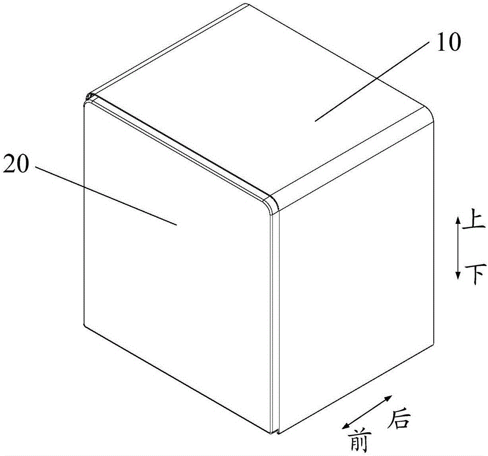
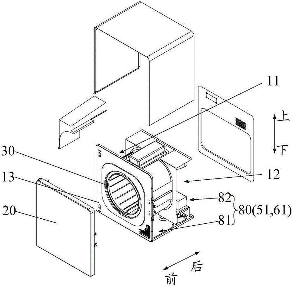
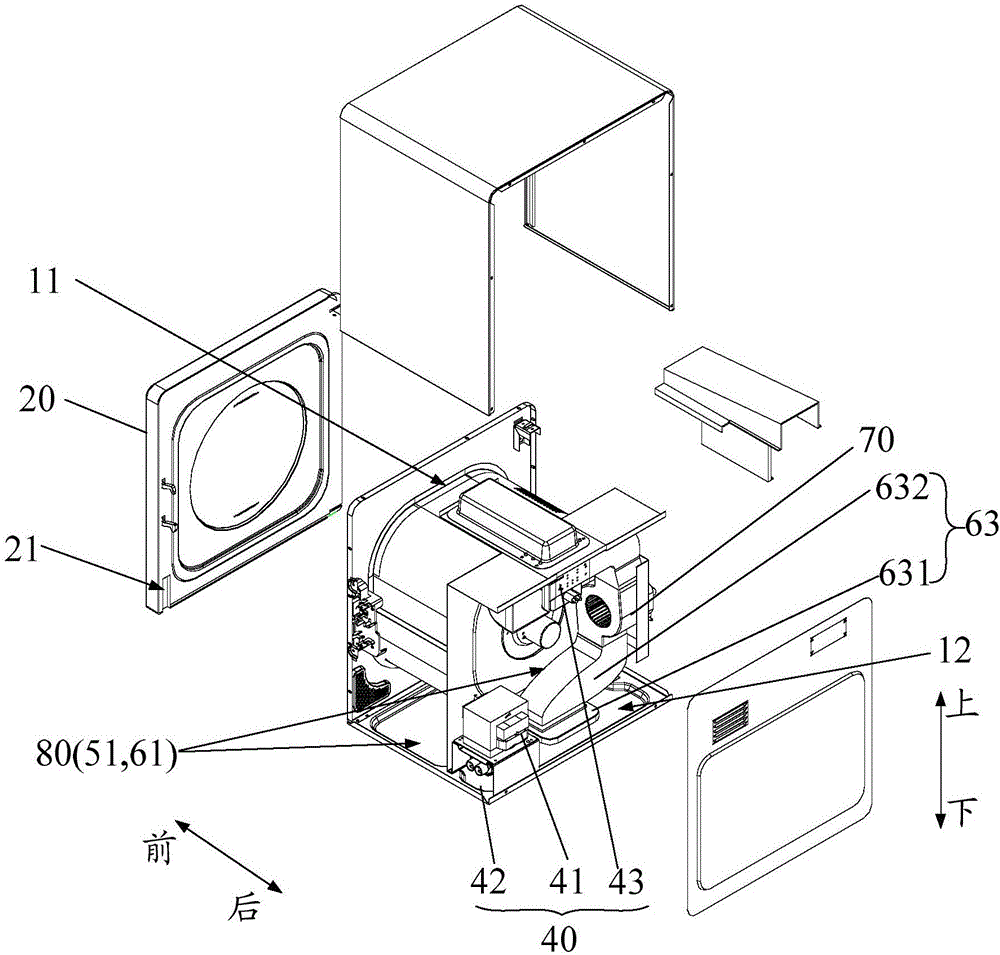
[0040] Such as Figure 1 to Figure 6 As shown, the microwave dryer provided by the present invention includes: a body 10 , a drying cavity 14 , a door assembly 20 , a drum 30 , electrical components...


PUM


Abstract

The invention provides a microwave dryer. The microwave dryer comprises a machine body, a door body assembly, a rotating drum, a plurality of electric devices, a cooling air duct, a baking air duct and a fan device, wherein the cooling air duct comprises a cooling air inlet duct and a cooling air outlet duct which communicate with each other, and the electric devices are arranged in the cooling air duct; the baking air duct comprises a baking air inlet duct, a baking air outlet duct and a communicating air duct. According to the microwave dryer provided by the invention, the microwave dryer comprises the baking air duct and the cooling air duct, air outside the microwave dryer is sucked into the two air ducts by the fan device, the electric devices are arranged in the cooling air duct, and wind in the cooling air duct is used for cooling the electric devices, so that the probability that the temperature of the electric devices is too high is lowered, and then, the service lives of the electric devices are prolonged; air in the baking air duct is introduced into a baking chamber by the baking air duct, and water vapor in the baking chamber is taken out of the baking chamber and is discharged from the machine body, so that matters to be baked in the rotating drum are baked.

Description

technical field [0001] The invention relates to the field of household appliances, in particular to a microwave dryer. Background technique [0002] The dryers in the related art are divided into hot-air type and condensation type. The heat source of the hot-air type dryer is generally a metal heating pipe or a PTC ceramic heating pipe. Through the exhaust duct at the front of the lower part of the inner tank, the hot air formed by the heating pipe is sent into the inner tank, and the water vapor in the inner tank is sucked away and discharged to the outside. Because the penetration effect of the hot wind is limited, the clothes are in the drum. The hot air path is obstructed, and the drying speed is slow. It usually takes 2 hours to dry multiple pieces, and the utilization rate of single piece drying is too low, and the electrical components of the dryer need to be cooled by cooling components, resulting in a larger volume of the dryer. . Contents of the invention [00...

Claims


Application Information

Patent Timeline
Patent Type & Authority Applications(China)
IPC IPC(8): D06F58/02D06F58/04D06F58/26
CPCD06F58/02D06F58/04D06F58/266
Inventor 李伟刘君君唐相伟
Owner GUANGDONG MIDEA KITCHEN APPLIANCES MFG CO LTD
Learn More