Ignition device of combustor

An ignition device and burner technology, which is applied in the direction of combustion ignition, burner safety device, burner, etc., can solve the problems of long ignition time, low ignition success rate, high power required for ignition, etc., and achieve the reduction of ignition power, The effect of solving the low ignition success rate and improving the ignition success rate

Inactive Publication Date: 2017-02-01
昆明博远中菱科技有限公司
View PDF5 Cites 9 Cited by
  • Summary
  • Abstract
  • Description
  • Claims
  • Application Information

AI Technical Summary

Problems solved by technology

[0003] Aiming at the deficiencies of the prior art, the present invention provides an ignition device for a burner with reliable performance to solve the problems of low ignition success rate, long ignition time and high power required for ignition in existing ignition methods

Method used


Image

  • Ignition device of combustor
  • Ignition device of combustor

Examples


Embodiment Construction

[0014] The following will clearly and completely describe the technical solutions in the embodiments of the present invention with reference to the accompanying drawings in the embodiments of the present invention. Obviously, the described embodiments are only some, not all, embodiments of the present invention. Based on the embodiments of the present invention, all other embodiments obtained by persons of ordinary skill in the art without creative efforts fall within the protection scope of the present invention.

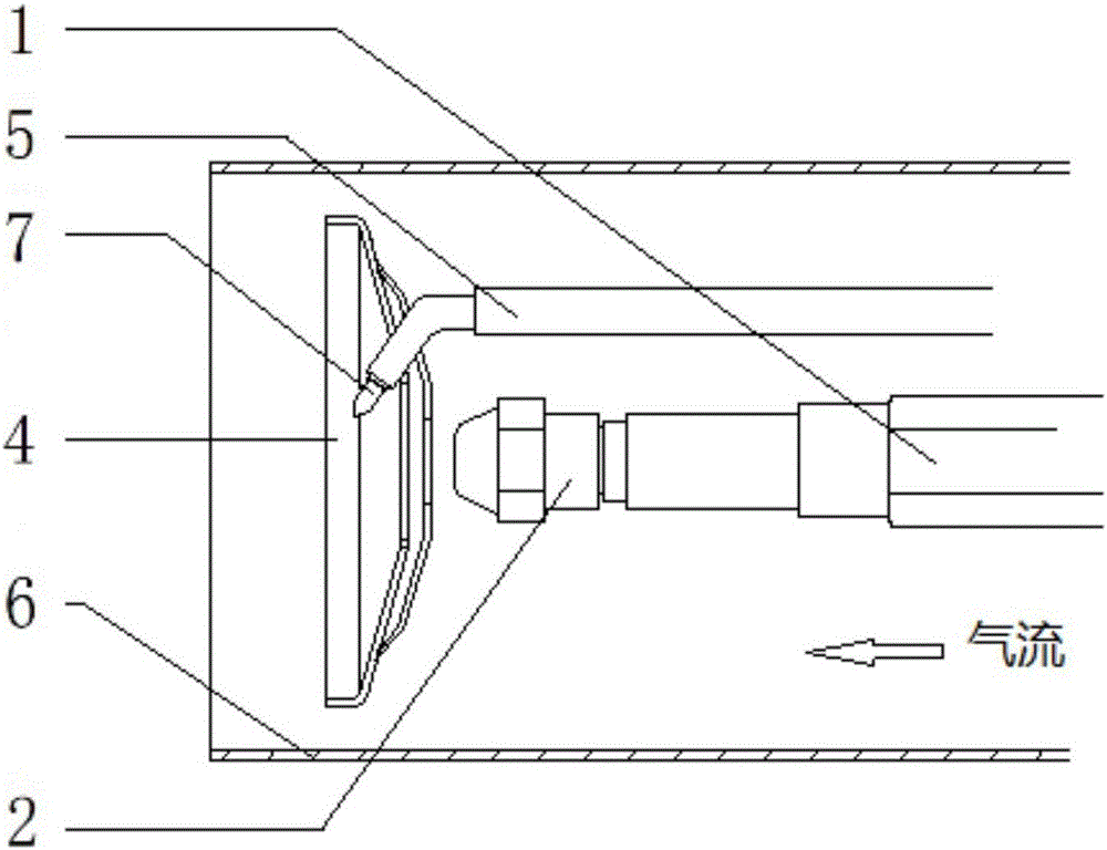
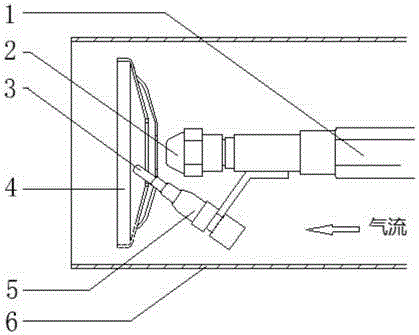
[0015] The working principle of the present invention is: the fuel nozzle 2, the flame stabilizing plate 4 and the ignition mechanism are sequentially arranged at the end of the blower tube 6 along the flow direction of the combustion air; The sprayed fuel is mixed in the swirling area downstream of the flame-stabilizing disc, and is ignited by the ignition mechanism to form a stable flame to ensure continuous and stable combustion of the burner. Various igniters w...


PUM


Abstract

The invention relates to the technical field of combustors, in particular to an ignition device of a combustor. The ignition device is sequentially provided with a fuel conveying device, a fuel nozzle, a flame stabilizing disc and an ignition mechanism in the combustion supporting air flowing direction at the tail end of an air supply cylinder. The flame stabilizing disc is provided with multiple oblique grooves, and a rotational flow area is generated after the combustion supporting air passes through the oblique grooves. The ignition mechanism is located at the position, on the downstream part of the flame stabilizing disc, in the rotational flow area and is deflected from the position of the center line of the fuel nozzle. The ignition device is scientific and reasonable in structural design, and the problems that in an existing ignition method, the ignition success rate is not high, the ignition time is long and the power needed for ignition is large are solved. The rotational flow area is generated by the combustion supporting air through the oblique grooves of the flame stabilizing disc, and the combustion supporting air is mixed with fuel injected by the nozzle in the position, on the downstream part of the flame stabilizing disc, of the rotational flow area, the mixture is ignited through the ignition mechanism to form stable flames, and continuous and stable combustion of the combustor is ensured. The ignition success rate is greatly increased, the ignition time is shortened, and the ignition power is also greatly reduced.

Description

technical field [0001] The patent of the present invention relates to the technical field of burners, in particular to an ignition device for a burner. Background technique [0002] A burner is a device that converts the chemical energy of fuel into heat energy by combustion. Existing burners usually adopt a gun-type structure, and the combustion-supporting air provided by the centrifugal fan is sent into the air duct. A fuel delivery device is installed on the center line of the air duct, and fuel nozzles, ignition nozzles, and ignition nozzles are sequentially installed at the end of the air duct along the flow direction of the combustion air. The fuel is sprayed out by the nozzle and then ignited by the ignition device. The combustion air passes through the chute of the flame stabilization plate to generate a swirling flow and forms a stable flame downstream of the flame stabilization plate to ensure continuous and stable combustion of the burner. The burner ignition met...

Claims


Application Information

Patent Timeline
Patent Type & Authority Applications(China)
IPC IPC(8): F23D14/46F23D14/26F23Q7/10F23Q3/00
CPCF23D14/46F23D14/26F23D2209/20F23Q3/002F23Q3/008F23Q7/10
Inventor 蔡梦尧冯勇王也
Owner 昆明博远中菱科技有限公司
Why Eureka
Try Eureka