Method and device for measuring modulation transfer function of telephoto lens through concave mirror imaging
A technology of modulation transfer function and imaging measurement, which is applied in the direction of measuring devices, optical instrument testing, and testing optical performance, etc. It can solve the problems that the small field of view telephoto lens cannot be measured and the measurement speed is fast, and achieves fast measurement speed and simple structure , The effect of low manufacturing cost
- Summary
- Abstract
- Description
- Claims
- Application Information
AI Technical Summary
Problems solved by technology
Method used
Image
Examples
specific Embodiment approach 1
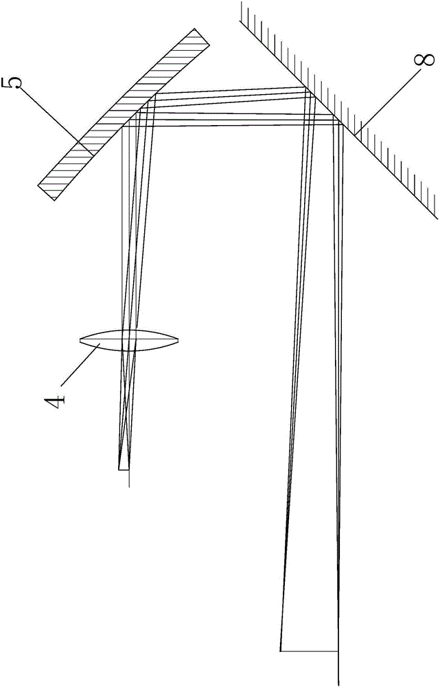
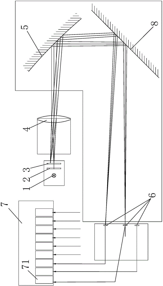
[0038] Such as Figure 1-4 As shown, the method for measuring the modulation transfer function of a telephoto lens by imaging a concave mirror provided by the present invention comprises the following steps:
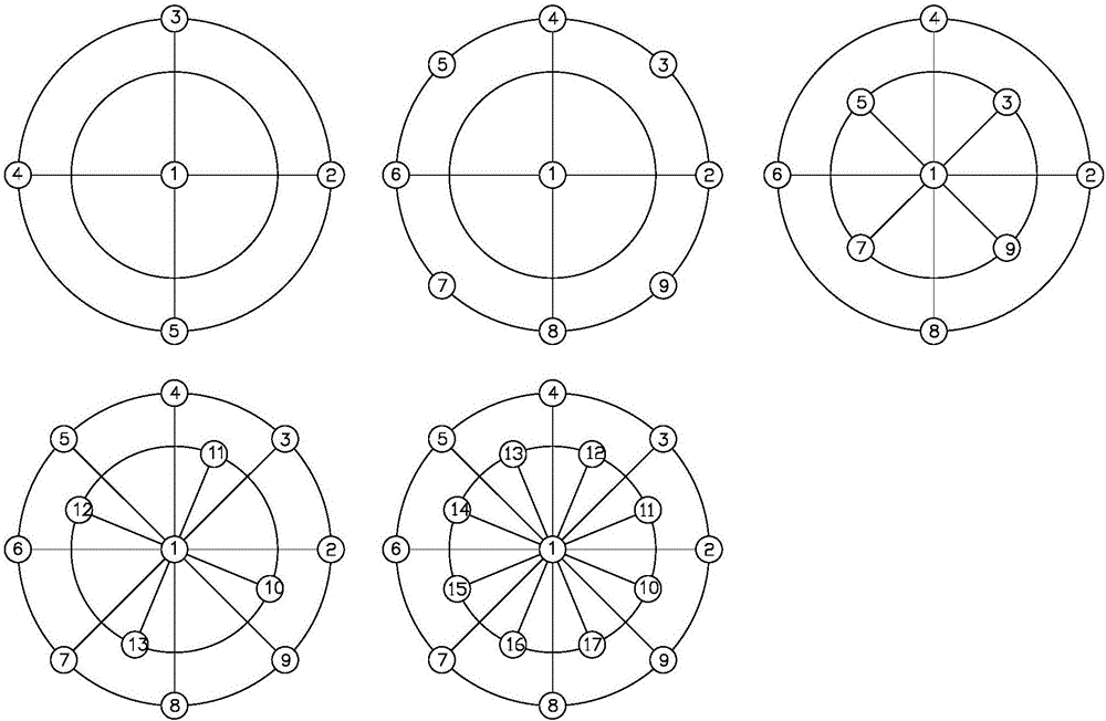
[0039] ①Place the light source 1, uniform light plate 2 and reticle 3 on the image side of the lens 4 under test and arrange them in sequence from far to near along the incident optical axis of the lens 4 under test. The reticle 3 is engraved with There are multiple groups of discrimination rate unit patterns composed of black and white thin lines arranged in the meridional and sagittal directions of different line pairs;
[0040] ② Place a concave reflector 5 with a focal length greater than the focal length of the lens under test 4 on the object side of the lens under test 4, so that the concave reflector 5 cooperates with the lens under test 4 to form an enlarged optical path, and the reflection of the concave reflector 5 Facing the optical axis of the lens under tes...
specific Embodiment approach 2
[0050] Such as Figure 1-4 As shown, it is a device for realizing the method for measuring the modulation transfer function of a telephoto lens by concave mirror imaging provided by the present invention. The direction of the incident optical axis of the lens 4 is a light source 1, a uniform light plate 2, and a reticle 3 arranged in sequence from far to near. The reticle 3 is engraved with multiple groups of black and white lines arranged in the meridional and sagittal directions of different line pairs. The discrimination rate unit pattern composed of thin lines, the device also includes a position adjustment device for adjusting the position of the reticle 3 relative to the lens 4 under test, and a device arranged on the object side of the lens under test for cooperating with the lens 4 under test to form a A concave reflector 5 for enlarging the optical path, a plurality of image sensors 6 distributed on the focal plane of the concave reflector 5 according to the measureme...
PUM
 Abstract
Description
Claims
Application Information
 - R&D
- Intellectual Property
- Life Sciences
- Materials
- Tech Scout
- Unparalleled Data Quality
- Higher Quality Content
- 60% Fewer Hallucinations
Browse by: Latest US Patents, China's latest patents, Technical Efficacy Thesaurus, Application Domain, Technology Topic, Popular Technical Reports.
© 2025 PatSnap. All rights reserved.Legal|Privacy policy|Modern Slavery Act Transparency Statement|Sitemap|About US| Contact US: help@patsnap.com


