Manual welding and clamping device

A technology of welding clips and clips, applied in auxiliary devices, welding equipment, auxiliary welding equipment, etc., can solve the problems of wasting time, reducing the production efficiency of enterprises, inconvenient disassembly, etc., so as to reduce factory costs, save time, and facilitate operation. Effect

Inactive Publication Date: 2017-02-08
周峰
View PDF5 Cites 2 Cited by
  • Summary
  • Abstract
  • Description
  • Claims
  • Application Information

AI Technical Summary

Problems solved by technology

[0002] At present, in the field of welding technology, welding technology is a method of connecting two or more base materials (workpieces to be welded) into a whole through the principle of resistance welding under high temperature or high pressure conditions. At present, in automobile manufacturing In the field, nuts and shells or other parts will be welded, which is convenient to use. Nut welding machines are used. When welding existing nut welding machines, fixtures need to be fixed on the frame, and bolts are usually used for fixing. , it is inconvenient to disassemble after fixing. When welding other parts, the fixture needs to be replaced. Replacing the fixture will waste a lot of time and reduce the production efficiency of the enterprise.

Method used


Image

  • Manual welding and clamping device
  • Manual welding and clamping device

Examples


Embodiment Construction

[0014] The present invention will be described in detail below with reference to the accompanying drawings and in combination with embodiments.

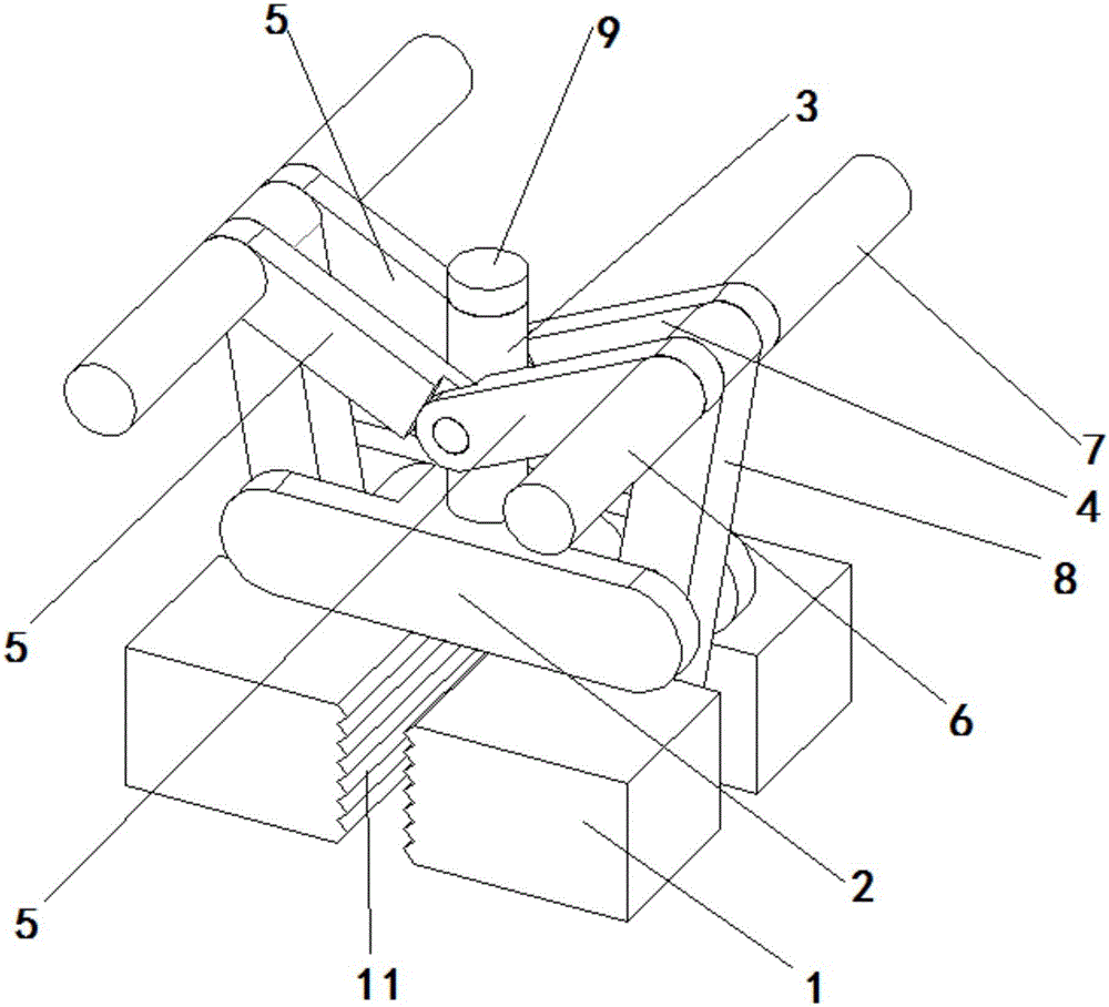
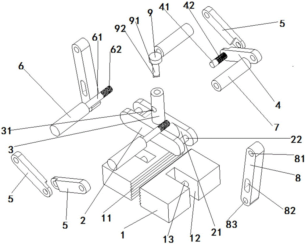
[0015] Such as Figure 1 to Figure 2 The shown manual welding clamping device includes a base 2, and the two ends of the base 2 are symmetrically provided with installation grooves 21, and a rotating shaft 22 is arranged in the installation groove 21, and a fixed cylinder 3 is fixed directly above the base 2, and the fixed cylinder 3. There is a positioning hole 31 horizontally in the middle, a top cover 9 is installed above the fixed cylinder 3, a positioning shaft 91 is arranged below the top cover 9, a limit plate 92 is provided at the bottom of the positioning shaft 91, and a main rotating plate is installed on the front side of the fixed cylinder 3. 4. An installation shaft 41 is provided at one end of the inner side of the main rotating plate 4, and a ring-shaped tooth groove 42 is arranged in the middle of the installation sha...


PUM


Abstract

The invention discloses a manual welding and clamping device which comprises a base. Installing grooves are symmetrically formed in the two ends of the base. A rotating shaft is arranged in each installing groove. A fixed cylinder is fixed right above the base. A locating hole is horizontally formed in the middle of the fixed cylinder. A top cover is installed on the upper portion of the fixed cylinder. A locating shaft is arranged below the top cover. A limiting piece is arranged at the bottom end of the locating shaft. A main rotating plate is installed on the front side of the fixed cylinder. An installing shaft is arranged at one end of the inner side of the main rotating plate. A tooth groove surrounding the installing shaft by one circle is formed in the middle of the installing shaft. The installing shaft is installed in the locating hole. Two auxiliary rotating plates with the structure the same as that of the main rotating plate are hinged to the tail end of the installing shaft, wherein the two auxiliary rotating plates are arranged symmetrically. Auxiliary rotating plates are symmetrically arranged on the outer side of the main rotating plate. The manual welding and clamping device can achieve fast disassembling and clamping, fast error correction can be achieved through a workpiece detector and a nut detector, operation is convenient, generation of inferior-quality products is reduced, time is saved, the working efficiency of a welding machine is improved, and the ex-factory cost of the products is reduced.

Description

technical field [0001] The invention relates to the field of clamps, in particular to a manual welding clamping device. Background technique [0002] At present, in the field of welding technology, welding technology is a method of connecting two or more base materials (workpieces to be welded) into a whole through the principle of resistance welding under high temperature or high pressure conditions. At present, in automobile manufacturing In the field, nuts and shells or other parts will be welded, which is convenient to use. Nut welding machines are used. When the existing nut welding machines are welded, the fixture needs to be fixed on the frame, and the bolt connection is usually used. , It is inconvenient to disassemble after fixing. When other parts are welded, the fixture needs to be replaced. Replacing the fixture will waste a lot of time and reduce the production efficiency of the enterprise. Contents of the invention [0003] The purpose of the present inventi...

Claims


Application Information

Patent Timeline
Patent Type & Authority Applications(China)
IPC IPC(8): B23K37/04
CPCB23K37/0443B23K2101/006
Inventor 周峰
Owner 周峰
Why Eureka
Try Eureka