A billet speed measuring jet printer

A jet printing machine and billet technology, applied in printing, typewriters, printing devices, etc., can solve problems such as inaccurate speed measurement, printing position, and adverse effects of printing speed, so as to improve the leveling quality, accurate and reliable speed measurement data, and improve The effect of flatness

Active Publication Date: 2019-03-08
SHANTOU JUNGUO MECHANICAL & ELECTRICAL TECH CO LTD
View PDF7 Cites 0 Cited by
  • Summary
  • Abstract
  • Description
  • Claims
  • Application Information

AI Technical Summary

Problems solved by technology

The inkjet printing equipment needs to print the moving billet synchronously during printing, so a speed measuring device is needed to feed back the moving speed of the billet to the processor, and then the processor controls the inkjet printer to print the billet, but due to Due to the high temperature characteristics of the steel billet, if the speed measuring device is in direct contact with the high temperature steel billet, not only the speed measurement will be inaccurate, but also the printing position and printing speed will be adversely affected

Method used


Image

  • A billet speed measuring jet printer
  • A billet speed measuring jet printer
  • A billet speed measuring jet printer

Examples


Embodiment Construction

[0022] In order to enable the review committee to have a further understanding of the purpose, features and functions of the present invention, the preferred embodiments are hereby given in detail in conjunction with the drawings as follows:

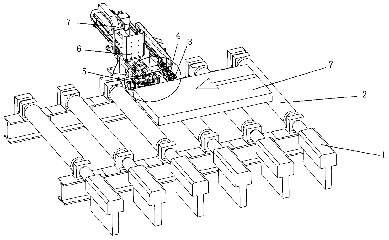
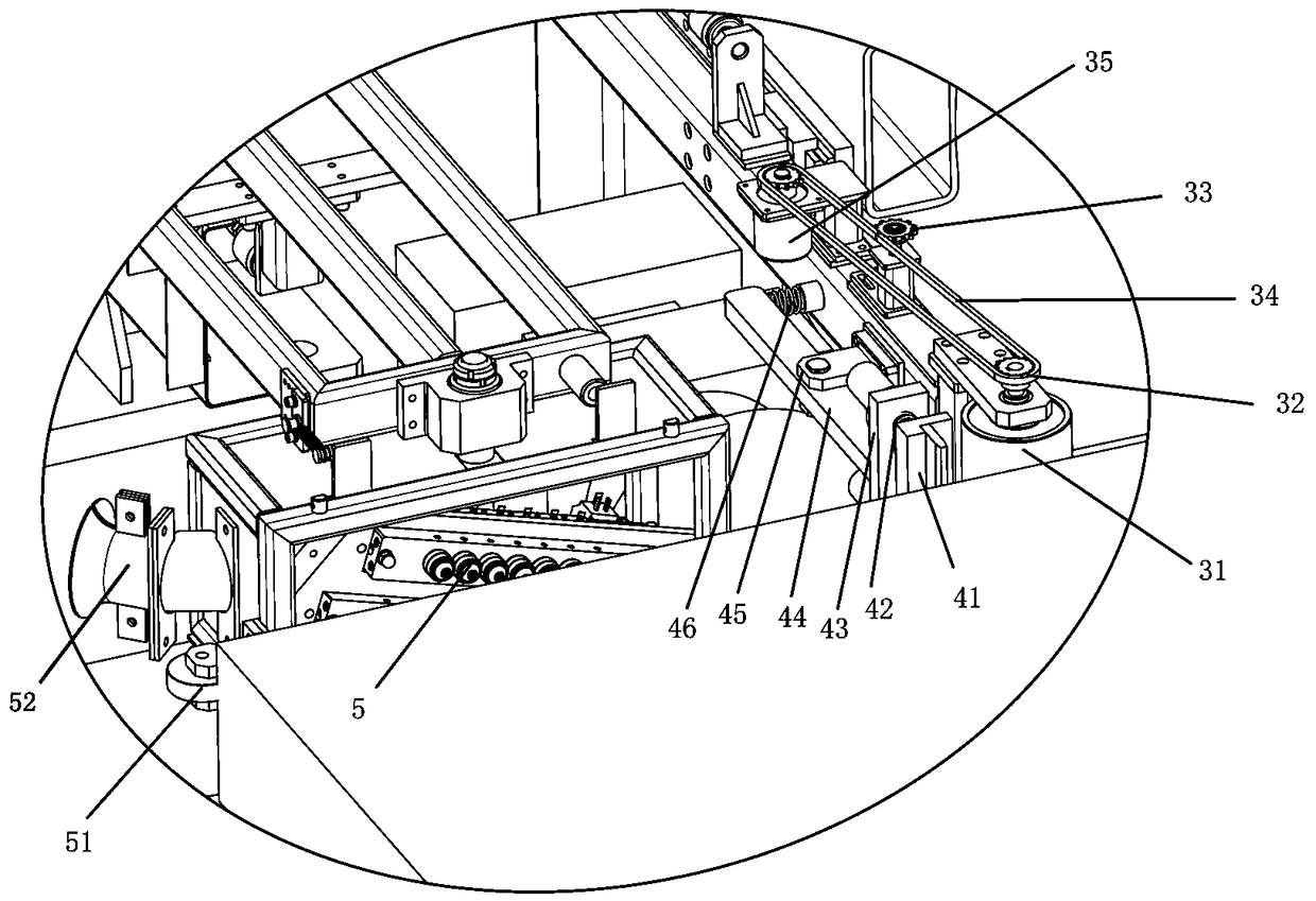
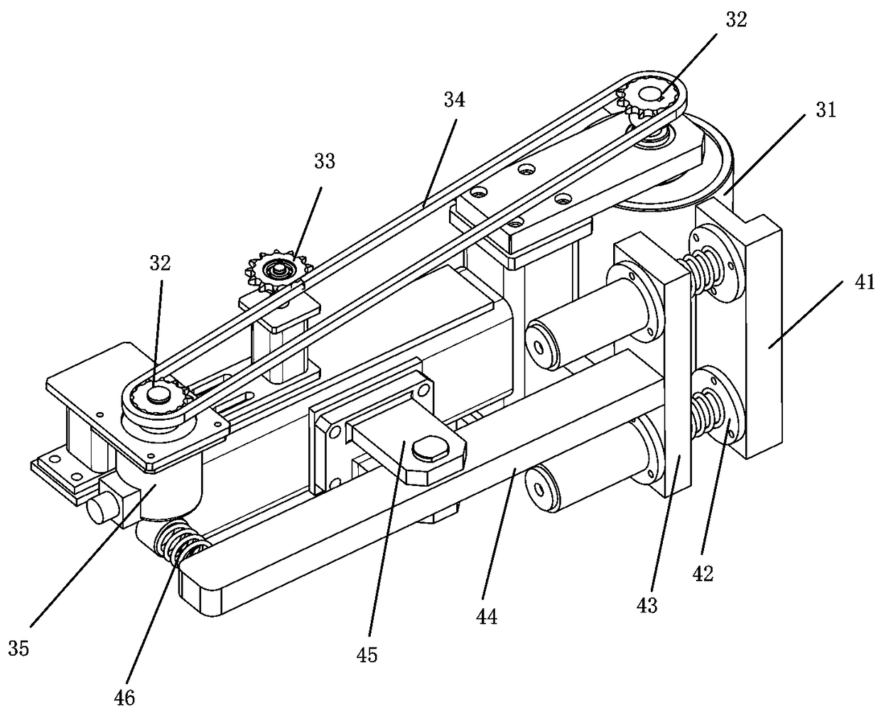
[0023] see Figure 1-3 As shown, it is a structural schematic diagram of a preferred embodiment of the present invention. The present invention is a steel billet speed measuring spray printing machine. A speed measuring device 3 is arranged on one side of the steel billet 7, and the speed measuring device 3 is driven by the steel billet 7 in progress. Rotating roller 31, the rotating roller 31 feeds back the rotation rate to the speed sensor 35 through the connecting device. The connecting device is composed of a belt gear 32 and a belt 34. The two belt gears 32 are installed on the rotating roller 31 and the speed sensor 35 respectively. When moving, the rotating roller 31 in contact with it rotates synchronously, and the belt gear 32 o...


PUM


Abstract

The invention relates to a steel accessory marking device, and particularly relates to a hot steel billet speed measurement jet printing marking machine. The characteristics lie in that one side of a steel billet is provided with a speed measurement device, the speed measurement device drives a rotating roller through the proceeding steel billet, the rotating roller feeds back the rotation rate to a speed measurement sensor through a connecting device, the connecting device is composed of a belt gears and a belt, and the two belt gears are installed on the rotating roller and the speed measurement sensor respectively; and one side of the speed measurement device is provided with a descaling device, a scraping plate of the descaling device presses against the steel billet, a turning fine adjustment device is arranged between the scraping plate and a transition plate, and transverse stress adjustment is performed on one side of a support plate on the transition plate through a spring device. According to the invention, data is transmitted to the speed measurement sensor by using the rotating roller, so that the speed measurement sensor is avoided from being contacted with the high-temperature steel billet, speed measurement data is ensured to be more accurate and more reliable, and data distortion caused by the high temperature is avoided; and the descaling device removes an oxidation part of the steel billet before jet printing, so that the surface evenness of the steel billet is improved, and the mark printing quality is improved.

Description

technical field [0001] The invention relates to a marking device for steel fittings, in particular to a speed-measuring jet-printing marking machine for hot steel billets. Background technique [0002] Steel billets are crude steels mainly used to make finished steel such as section steel, wire rods, and plates. Crude steel is a finished steel billet that is processed by molten iron and added with alloys, carbon and other elements. In the iron and steel industry, in the process of continuous steelmaking, hot rolling, and heat treatment of billets, ingots and metal materials, it is very easy to cause mixed steel accidents due to unclear markings, so billets need to be marked. The inkjet printing equipment needs to print the billet in progress synchronously during printing, so a speed measuring device is needed to feed back the moving speed of the billet to the processor, and then the processor controls the inkjet printer to print the billet, but due to Due to the high temper...

Claims


Application Information

Patent Timeline
Patent Type & Authority Patents(China)
IPC IPC(8): B41J2/01B41J3/44B41J29/393B22D31/00B41J3/413
CPCB22D31/00B41J2/01B41J3/413B41J3/445B41J29/393
Inventor 罗俊生
Owner SHANTOU JUNGUO MECHANICAL & ELECTRICAL TECH CO LTD
Why Eureka
Try Eureka