Pantograph control device and railway vehicle

A control device and pantograph technology, applied in the field of rail transit, can solve problems such as poor safety and low transmission efficiency, and achieve the effects of increased life, simple structure, improved transmission efficiency and safety

Active Publication Date: 2017-02-08
CRRC TANGSHAN CO LTD
View PDF6 Cites 12 Cited by
  • Summary
  • Abstract
  • Description
  • Claims
  • Application Information

AI Technical Summary

Problems solved by technology

[0005] The invention provides a pantograph control device and a rail vehicle to solve the technical problems of low transmission efficiency and poor safety of the pantograph control circuit in the prior art

Method used


Image

  • Pantograph control device and railway vehicle
  • Pantograph control device and railway vehicle
  • Pantograph control device and railway vehicle

Examples


Embodiment 1

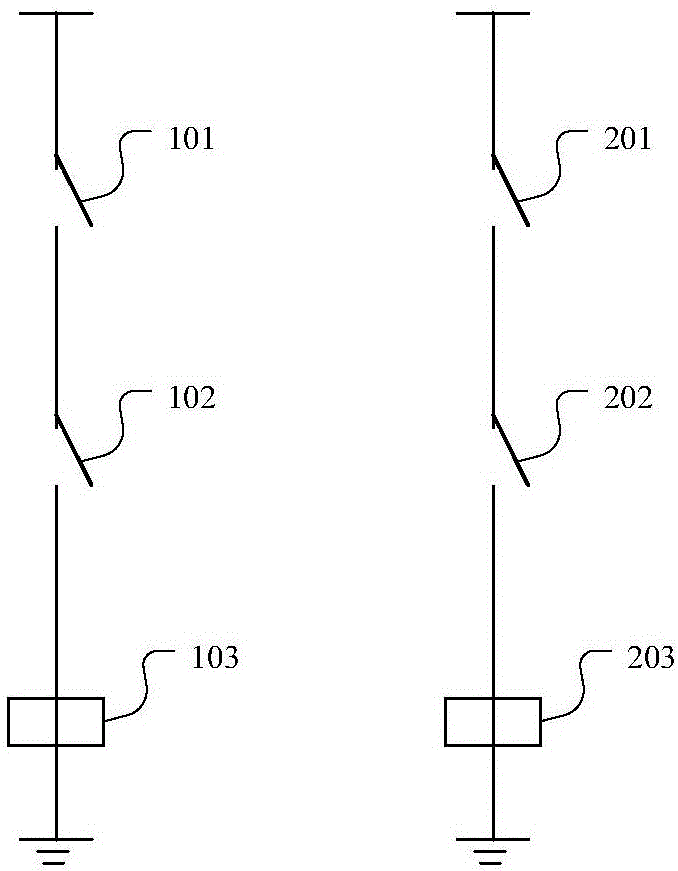
[0063] Embodiment 1 of the present invention provides a pantograph control device. figure 1 It is a schematic diagram of a pantograph control device provided in Embodiment 1 of the present invention. Such as figure 1As shown, the pantograph control device in this embodiment may include two pantograph control circuits, and the two pantograph control circuits are respectively used to control the lowering of the pantographs on both sides.

[0064] Wherein, the pantograph control circuit on the left may include: a first control switch 101, a first primary relay 103, and a first primary relay switch 102 arranged in series; the first control switch 101 or the first When the primary relay switch 102 on the opposite side is disconnected, the first primary relay 103 is de-energized; the first control switch 101 is used to close or disconnect under the operation of the user; the first primary relay 103 is used to The lowering of the pantograph is controlled when power is lost; the fir...

Embodiment 2

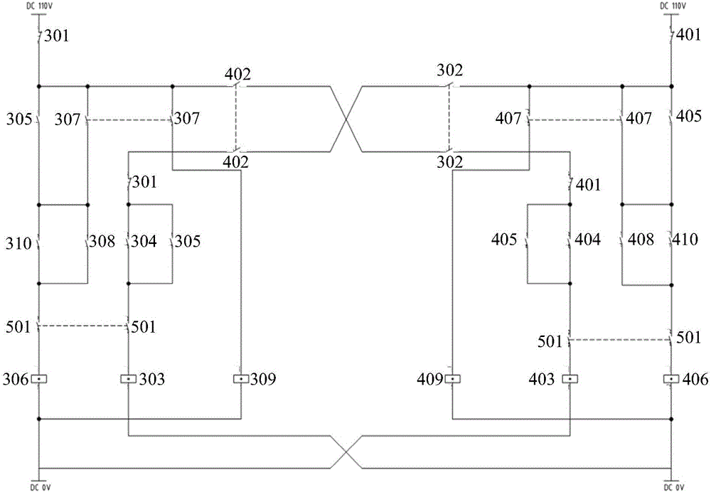
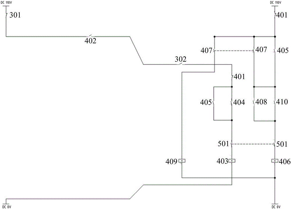
[0078] Embodiment 2 of the present invention provides a pantograph control device. figure 2 It is a schematic diagram of a pantograph control device provided by Embodiment 2 of the present invention. Such as figure 2 As shown, the pantograph control device in this embodiment may include two pantograph control circuits, and the two pantograph control circuits are respectively used to control the lowering of the pantographs on both sides.

[0079] In this embodiment, the pantograph control circuit on the left can be used to control one pantograph, and the pantograph control circuit on the right can be used to control another pantograph.

[0080] Wherein, the left pantograph control circuit may include: a third control switch, and the third control switch may include a third driver's emergency shutdown button 301 arranged in the driver's cab. The pantograph control circuit may further include: a third pantograph state monitoring switch 302, a third primary relay 303, a third ...

Embodiment 3

[0110] Embodiment 3 of the present invention provides a rail vehicle, including the pantograph control device described in any one of the above embodiments.

[0111] Wherein, the number of the pantographs may be two, and the two pantograph control circuits in the pantograph control device may be used to control the lowering of the two pantographs respectively.

[0112] In this embodiment, the structures and functions of the components of the rail vehicle are similar to those of the foregoing embodiments, and will not be repeated here.

[0113] The rail vehicle provided in this embodiment includes two pantograph control circuits, and each pantograph control circuit may include: a control switch arranged in series, a primary relay and an opposite primary relay switch, and the control switch can be controlled by the user The pantograph is disconnected under the operation of the primary relay, and the lowering of the pantograph is realized through the primary relay. The simultane...


PUM


Abstract

The invention provides a pantograph control device and a railway vehicle. The pantograph control device comprises two pantograph control circuits which are respectively used for controlling the pantograph descending on the two sides, wherein each of the pantograph control circuits comprises a control switch, a primary relay and an opposite-side primary relay switch which are serially arranged; when the control switch or the opposite-side primary relay switch is switched off, the primary relay is powered off; the control switch is switched on or off under the operation of a user; the primary relay is used for controlling the pantograph descending under a powered off state; the opposite-side primary relay switch is controlled by an opposite-side primary relay and is switched off when the opposite-side primary relay is powered off. The pantograph control device and the railway vehicle provided by the invention have the advantages that the structure is simple, the complex network device is not required, the transmission efficiency and the safety are promoted, the simultaneous descending of the pantographs on the two sides can be realized and the service life of the pantographs can be prolonged.

Description

technical field [0001] The invention relates to rail transit technology, in particular to a pantograph control device and a rail vehicle. Background technique [0002] The pantograph is an electrical device in a rail vehicle that obtains electrical energy from the catenary. It is generally installed on the roof and plays an important role in the normal operation of the vehicle. [0003] When an emergency occurs during the operation of the vehicle, such as the pantograph cannot be lowered normally, and the main circuit breaker cannot be opened normally, it is necessary to lower the pantograph through the pantograph shutdown control circuit. [0004] At present, the pantograph shut-off control circuit mostly relies on the network to control the pantograph. The transmission path of the circuit control signal is long and passes through many devices. The pantograph function cannot be executed or mis-executed, resulting in low transmission efficiency of the control circuit and hi...

Claims


Application Information

Patent Timeline
Patent Type & Authority Applications(China)
IPC IPC(8): B60L5/28
CPCB60L5/28
Inventor 宋立群李小军符建民付磊吴宏彬
Owner CRRC TANGSHAN CO LTD
Why Eureka
Try Eureka