
Sleeper replacing machine with swinging rail lifting device

A sleeper and mechanical technology, applied in the field of sleeper changing machinery, can solve the problems of sleeper sinking, time-consuming and labor-intensive, and low work efficiency

Inactive Publication Date: 2017-02-08
KUNMING UNIV
View PDF0 Cites 0 Cited by
  • Summary
  • Abstract
  • Description
  • Claims
  • Application Information

AI Technical Summary

Problems solved by technology

[0002] During the long-term use of railway sleepers, due to natural settlement and vibration, some railway sleepers sink and need maintenance. Individual sleepers are damaged and need to be replaced in time. In the process of sleeper replacement, manual work is used, which is time-consuming and laborious. , the work efficiency is low, and the work cannot be completed within the effective train passage gap (commonly known as: skylight)

Method used


Image

  • Sleeper replacing machine with swinging rail lifting device
  • Sleeper replacing machine with swinging rail lifting device
  • Sleeper replacing machine with swinging rail lifting device

Examples


Embodiment Construction

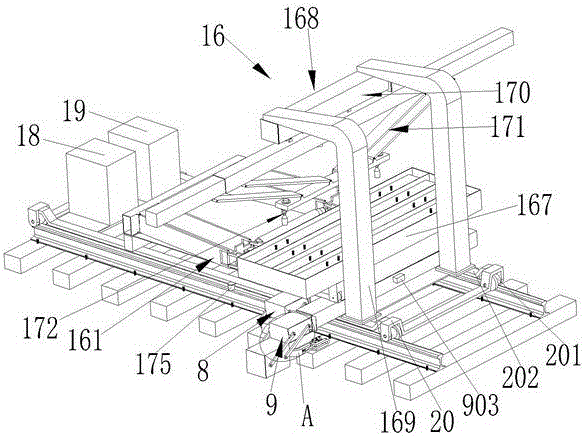
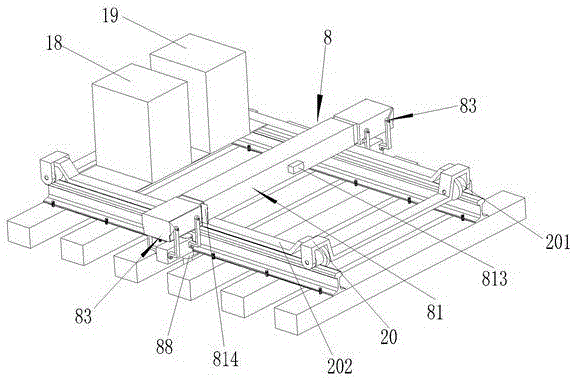
[0065] see figure 1 Shown, the present invention is made up of rail device 8, rail transition and push-pull sleeper device 9, sleeper hoisting device 16, generator 18, hydraulic system and control system box 19 and rail car 20. The rail car is provided with a plurality of casters 201 and two longitudinal beams 202. The rail lifting device 8, the rail transfer and push-pull sleeper device 9, the sleeper lifting device 16, the generator 18, the hydraulic system and the control system box 19 are arranged on the second side of the rail car. On a longitudinal beam 202, the rail car 20 is pulled by an engineering vehicle, the generator 18 provides power for the oil pump and the control system, and the hydraulic system and the control system box 19 are provided with a fuel tank, an oil pump, a hydraulic control system and an automatic control system;

[0066] see Figure 2 to Figure 5 As shown, the described rail lifting device 8 is composed of a first telescopic assembly 81, a firs...


PUM


Abstract

The invention discloses a sleeper replacing machine with a swinging rail lifting device. The sleeper replacing machine is composed of the rail lifting device, a sleeper-rotating and sleeper pushing-and-pulling device, a sleeper hoisting device, a generator, a hydraulic system and control system cabinet and a rail car. The rail car is provided with a plurality of trundles and two longitudinal beams. The rail lifting device, the sleeper-rotating and sleeper pushing-and-pulling device, the sleeper hoisting device, the generator and the hydraulic system and control system cabinet are arranged on the two longitudinal beams of the rail car. The rail car is dragged by an engineering truck. The generator supplies power to oil pumps and control systems. An oil tank, the oil pumps, the hydraulic control system and the automatic control system are arranged in the hydraulic system and control system cabinet. According to the sleeper replacing machine, the working devices can be aligned with working positions automatically and rapidly; the sleeper replacing machine can adapt to corresponding operations for sleeper replacing of linear and curved railway sections; and the sleeper-rotating and sleeper pushing-and-pulling device is an integrated device, and is simple in structure, convenient to operate and high in sleeper replacing efficiency, and automatic control is achieved.

Description

technical field [0001] The invention relates to a railway maintenance machine, in particular to a pillow changing machine with a swing rail lifting device. Background technique [0002] During the long-term use of railway sleepers, due to natural settlement and vibration, some railway sleepers sink and need maintenance. Individual sleepers are damaged and need to be replaced in time. In the process of sleeper replacement, manual work is used, which is time-consuming and laborious. , the work efficiency is low, and the work cannot be completed in the effective train passage gap (commonly known as: skylight). Contents of the invention [0003] The purpose of the present invention is to provide a pillow changing machine with a swing rail lifting device. [0004] The invention is composed of a rail lifting device, a rail switching and push-pull sleeper device, a sleeper hoisting device, a generator, a hydraulic system, a control system box and a rail car. The rail car is equ...

Claims


Application Information

Patent Timeline
IPC IPC(8): E01B29/10
CPCE01B29/10
Inventor 徐若瑜于向军
Owner KUNMING UNIV
Learn More