A hoop and beam type support device for reactor pressure vessel

A technology of pressure vessels and hoops and beams, applied in reactors, nuclear power generation, nuclear engineering, etc., can solve problems such as weak earthquake resistance, and achieve the effect of simple structure, convenient construction, and strong earthquake resistance

Active Publication Date: 2018-05-08
NUCLEAR POWER INSTITUTE OF CHINA
View PDF6 Cites 0 Cited by
  • Summary
  • Abstract
  • Description
  • Claims
  • Application Information

AI Technical Summary

Problems solved by technology

The object of the present invention is to provide a hoop and beam-type support device for a reactor pressure vessel. By setting a cross-tension beam and a hoop surrounding the outer surface of the pressure vessel, one end of the cross-tension beam is connected to the hoop, and the other end is limited to In the concrete foundation in the reactor pit, the technical problem of the high-flux test reactor pressure vessel with a relatively large length and diameter is flexibly swayed and the earthquake resistance is not strong.

Method used


Image

  • A hoop and beam type support device for reactor pressure vessel
  • A hoop and beam type support device for reactor pressure vessel
  • A hoop and beam type support device for reactor pressure vessel

Examples


Embodiment 1

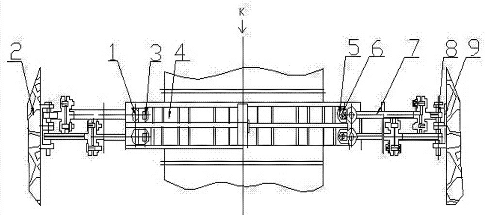
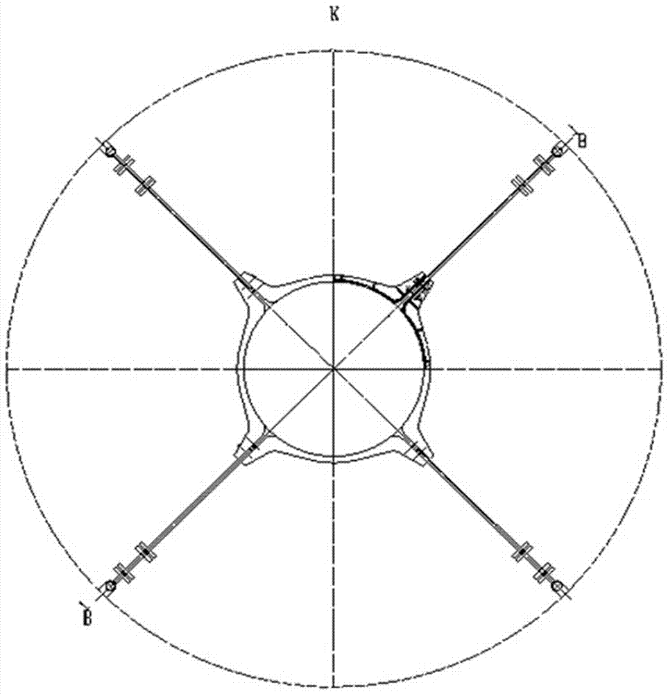
[0038] Such as figure 1 , figure 2 , image 3 As shown, the present invention is a hoop-stayed beam type support device for a reactor pressure vessel, comprising a concrete foundation 2, a hoop 4 encircling the upper part of the pressure vessel, and at least two sets of cross-stay beams 7 relatively arranged on the periphery of the pressure vessel. One end of the transverse tension beam 7 is connected with the hoop 4, and the other end is connected with the concrete foundation 2.

[0039] In the embodiment, the hoop 4 is a well-known device in the field, and its structure and principle are common knowledge in the field, and will not be further described here. The hoop 4 surrounds or surrounds the upper part of the outer surface of the reactor pressure vessel, and the cross-tension beams 7 are evenly arranged on the hoop 4 so as not to limit the axial thermal expansion of the pressure vessel. In this embodiment, the concrete foundation 2 is located in the reactor pit, and i...

Embodiment 2

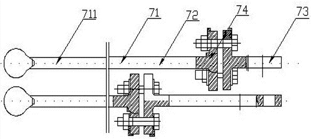
[0042] In this embodiment, on the basis of Embodiment 1, it is further defined that the cross-stay beam 7 is connected to the hoop 4 through the connecting pin 1 . There can be multiple ways to connect the tie beam 7 and the hoop 4, such as fixed connection and detachable connection. In this technical solution, it is preferably connected by a connecting pin 1, and the connecting pin structure can specifically be a cylindrical pin, a conical pin, a special-shaped The pins and the like can directly determine the mutual position between the connecting hoop 4 and the cross-tension beam 7, transmit a small load, and realize the tight connection of adaptability. Other structures and principles involved in this embodiment are the same as those in Embodiment 1, and will not be repeated here.

Embodiment 3

[0044] In this embodiment, on the basis of the above embodiments, it is further defined that a fastener is installed between the connecting pin 1 and the hoop 4, and the fastener is a connecting piece formed by detachable connection of the bolt 3 and the nut 5 . When the reactor pressure vessel is running, both the external force load and the load generated by the internal force during operation are relatively large. Therefore, for the high-flux test reactor reactor vessel, to avoid its unrecoverable flexible swing, the support device must have both Strong endurance and strong stability. The main factors affecting the connection stability are the components themselves and the stability of the connection between the two components. Among them, the materials of the hoops, transverse beams, connecting pins and other components are all made of workpieces with a certain rigidity or strength, which can meet the support requirements. function. In terms of the connection of component...


PUM


Abstract

The invention discloses a linear support device for a hoop tension beam for a reactor pressure vessel, which comprises a concrete foundation, a hoop surrounding the upper part of the pressure vessel, and at least two sets of transverse tension beams relatively arranged on the periphery of the pressure vessel. One end of the beam is connected with the hoop, and the other end is connected with the concrete foundation. The invention adopts hoops, cross-tension beams, connecting pins and other structures. The hoops surround the upper outer surface of the pressure vessel. One end of the cross-tension beam is connected to the hoop, and the other end is fixed in the concrete foundation of the reactor pit. It is connected with the hoop through connecting pins, while supporting the reactor pressure device, it can decompose the lateral stress of the pressure vessel during operation, eliminate the flexible swing of the vessel, and enhance the shock resistance of the reactor pressure vessel.

Description

technical field [0001] The invention relates to the technical field of support for reactor pressure vessels of nuclear power plants, in particular to a hoop and beam type support device for reactor pressure vessels. Background technique [0002] The reactor pressure vessel is one of the key equipment of the entire nuclear power plant reactor and the primary circuit system, and is an important part of the pressure boundary. structure etc. In the containment, in order to effectively fix the reactor pressure vessel and ensure the safe operation of the entire reactor, a supporting structure must be set. The weight of the entire nuclear power plant reactor is relatively large. The pressure and temperature of the coolant system will change between the operation and shutdown of the entire reactor. At the same time, the influence of seismic load should also be considered. Therefore, the support structure must be able to withstand the static pressure of the pressure vessel. Under t...

Claims


Application Information

Patent Timeline
Patent Type & Authority Patents(China)
IPC IPC(8): G21C13/024
CPCG21C13/024Y02E30/30
Inventor 何震陈富财田俊科甘斌谭波杜华罗英
Owner NUCLEAR POWER INSTITUTE OF CHINA
Why Eureka
Try Eureka