Dual stop band ultra-wideband antenna with steep stop band

An ultra-wideband antenna, dual stopband technology, applied in the direction of antenna, antenna coupling, antenna components, etc., can solve the problems of signal attenuation, inability to achieve steep edges, and the stopband is too wide, and achieve wide bandwidth and good broadband characteristics. , the effect of steep stopband edges

Inactive Publication Date: 2017-02-08
WENZHOU UNIVERSITY
View PDF1 Cites 4 Cited by
  • Summary
  • Abstract
  • Description
  • Claims
  • Application Information

AI Technical Summary

Problems solved by technology

However, most stopband technologies cannot achieve steep edges, and the stopband is too wide to attenuate the useful frequency band outside the band

Method used


Image

  • Dual stop band ultra-wideband antenna with steep stop band
  • Dual stop band ultra-wideband antenna with steep stop band
  • Dual stop band ultra-wideband antenna with steep stop band

Examples


Embodiment Construction

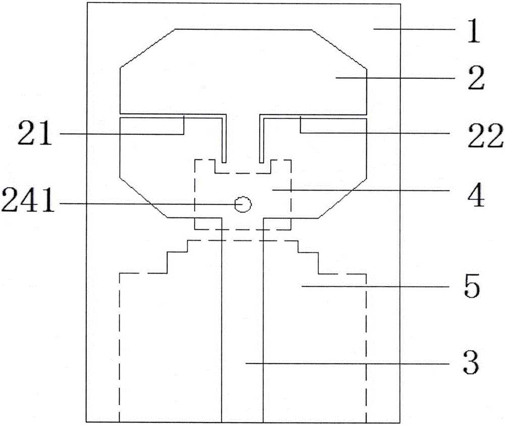
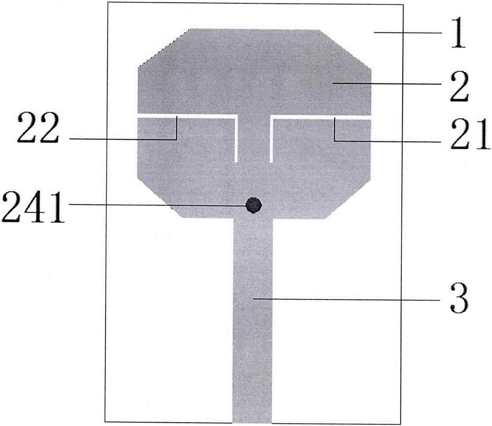
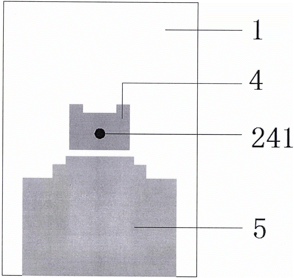
[0028] The present invention is an ultra-wideband antenna with double stop bands, its structure is as figure 1 , figure 2 , image 3 , Figure 4 As shown, the antenna includes a dielectric substrate (1), a radiation unit (2), a microstrip feeder (3), a back metal patch (4), a metal ground plate (5) and via holes (241). The radiation unit (2) and the microstrip feeder (4) are located on the upper surface of the dielectric substrate, and the back metal patch (4) and the metal grounding plate (5) are located on the lower surface of the dielectric substrate. The radiation unit (2) is located at the middle and upper part of the dielectric substrate (1), and is connected with the microstrip feeder (3) located at the middle and lower part. The back metal patch (4) and the metal grounding plate (5) are respectively located at the middle and middle lower part of the lower surface of the dielectric substrate. The via hole (241) connects the radiation unit (2) with the back metal pa...


PUM


Abstract

The invention discloses a dual stop band ultra-wideband antenna with a steep stop band, and the antenna comprises a dielectric substrate, a radiating element, a micro-strip feeder, a back metal patch, a metal ground plate and a via hole. Double L-shaped grooves are arranged on the radiating element, a rectangular groove is arranged on the back metal patch, and a step-type structure is on the metal ground plate. The radiating element and the micro-strip feeder are arranged on the upper surface of the dielectric substrate and are connected with each other. The back metal patch and the metal ground plate are arranged on the lower surface of the dielectric substrate, and the via hole connects the radiating element with the back metal patch. According to the invention, the antenna has steep edges of stop band characteristic, two stop bands are generated in WiMAX and WLAN frequency bands, and a problem that the antenna interference between an ultra-wideband wireless communication system and WLAN and WiMAX systems can be effectively solved.

Description

technical field [0001] The invention relates to the field of ultra-wideband (UWB) antennas, in particular to a double-stop-band UWB antenna with steep stop-bands. Background technique [0002] In February 2002, the Federal Communications Commission (FCC) of the United States officially approved the license-free frequency band that can be used by ultra-wideband communication systems as 3.1GHz to 10.6GHz. Since then, ultra-wideband communication technology has received extensive attention and has become the current short It is a research hotspot in distance wireless communication. [0003] Ultra-wideband technology has many advantages such as high transmission data rate, low transmission power, high security performance, and low cost. It is mainly used in indoor communication, high-speed wireless local area network, medical imaging, short-range radar and other fields. [0004] However, there are still some narrowband communication systems in the working frequency band of the ...

Claims


Application Information

Patent Timeline
Patent Type & Authority Applications(China)
IPC IPC(8): H01Q1/38H01Q1/50H01Q1/52H01Q5/25H01Q5/50
CPCH01Q1/38H01Q1/50H01Q1/521H01Q5/25H01Q5/50
Inventor 刘桂曾喆陈芸妮林威洪郅瑞行白晶
Owner WENZHOU UNIVERSITY
Why Eureka
Try Eureka