Supercharge Your Innovation With Domain-Expert AI Agents!

A photovoltaic module cleaning device

A technology for cleaning devices and photovoltaic modules, applied to photovoltaic modules, photovoltaic power generation, electrical components, etc., can solve problems such as angle deviation, limited water tank capacity, and low cleaning efficiency of a single robot

Active Publication Date: 2020-03-17
ZHEJIANG GUOZI ROBOT TECH
View PDF8 Cites 0 Cited by
  • Summary
  • Abstract
  • Description
  • Claims
  • Application Information

AI Technical Summary

Problems solved by technology

For the bottom surface cleaning vehicle, it has the following disadvantages: (1) The driving speed is slow; 2) The cleaning operation is complicated and requires high requirements for operators. When driving between the photovoltaic panel arrays, it is necessary to pay attention to the contact between the cleaning roller brush and the photovoltaic panel surface In some cases, the distance between the cleaning vehicle and the photovoltaic modules should remain unchanged, otherwise, the cleaning brush head cannot cover the entire height of the photovoltaic panel surface, resulting in missing the cleaning surface; Especially when there is a difference in height between the two sides of the track corresponding to the ground, it will cause the car body to roll. At this time, there is an angle deviation between the roller brush that was originally parallel to the mirror surface and the photovoltaic panel; (4) The ground cleaning vehicle is equipped with a cab , the cleaning task is carried out by manual driving, and personnel with excavator driving experience are required. Moreover, the chassis is driven by an internal combustion engine and requires manual refueling. The cleaning method consumes a lot of water, and the capacity of the water tank is limited. Not big, reciprocating and adding water takes a long time, and the cleaning efficiency is reduced again
However, the on-board cleaning robot has the following disadvantages: (1) The on-board cleaning robot can only work on a single-string board, and can only perform cross-string cleaning after the additional track connection transformation between strings , and even so, the plate cleaning robot can not complete the cross-row operation, so each row of photovoltaic panels is equipped with at least one cleaning robot; (2) If the terrain does not allow all connections between strings (the terrain in a single row has large fluctuations, climbing Slope requirements are high), then a single row of photovoltaic panels needs more than one panel cleaning machine; (3) The cleaning robot needs to have its own battery or a battery panel, the body is heavy, and the climbing ability and overall driving speed are not high, so a single robot The cleaning efficiency is low, and the terrain requirements for the arrangement of photovoltaic panel arrays are high
Therefore, for a photovoltaic array to achieve a full-coverage cleaning range, the number of on-board cleaning robots that need to be invested is relatively large. This data is directly proportional to the power generation capacity of the photovoltaic electric field, which will result in a large cost of fixed cleaning equipment. At the same time, the daily maintenance workload of large-scale board cleaning robots is relatively large
In addition, the failure rate of batch equipment increases. Once the failed machine cannot be transferred in time, the "hot spot effect" will burn a single photovoltaic panel, and in severe cases, it will cause the entire array to catch fire

Method used


Image

  • A photovoltaic module cleaning device
  • A photovoltaic module cleaning device
  • A photovoltaic module cleaning device

Examples


Embodiment Construction

[0030] The core of the present invention is to provide a photovoltaic module cleaning device, the photovoltaic module cleaning device has a board replacement function, and can effectively avoid the collision between the device and the photovoltaic board.

[0031] In order to enable those skilled in the art to better understand the solution of the present invention, the present invention will be further described in detail below in conjunction with the accompanying drawings and specific embodiments.

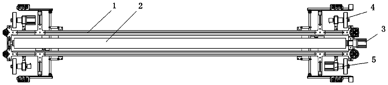
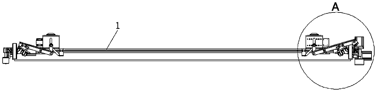
[0032] Please refer to Figure 1 to Figure 3 , figure 1 It is a bottom view of a specific embodiment of the photovoltaic module cleaning device provided by the present invention; figure 2 It is a front view of a specific embodiment of the photovoltaic module cleaning device provided by the present invention; image 3 for figure 2 Schematic diagram of the enlarged structure of part A of the photovoltaic module cleaning device shown.

[0033] In this embodiment, the photovolta...


PUM


Abstract

The invention discloses a photovoltaic module cleaning device, which includes an on-board cleaning machine. It is characterized in that it also includes a carrier that can lift the on-board cleaning machine and a mover for driving the carrier to move. The carrier and the on-board cleaning machine The cleaning machines are softly connected through connecting parts, and the on-board cleaning machine is equipped with a limiting part that can be connected with the photovoltaic panel. The photovoltaic module cleaning device provided by the present invention adds a carrier and a mover, and uses the carrier to lift the on-board cleaning machine, so that it can be moved to the next photovoltaic panel driven by the mover. The upper cleaning machine is provided with a limiting component, which can quickly connect the limiting component to the photovoltaic panel when the carrier is placing the on-board cleaning machine, thereby enabling rapid plate replacement of the on-board cleaning machine. In addition, the device also uses a soft connection between the carrier and the on-board cleaning machine to effectively reduce the degree of collision between the on-board cleaning machine and the photovoltaic panels, thereby reducing damage to the photovoltaic panels.

Description

technical field [0001] The invention relates to the field of photovoltaic module cleaning equipment, in particular to a photovoltaic module cleaning device. Background technique [0002] With the improvement of environmental protection requirements and sustainable energy demand, the proportion of clean energy in the total energy is increasing year by year, and the cleaning demand of photovoltaic modules is gradually heating up. [0003] There are two reasons for photovoltaic array cleaning: 1. Dirt will cause differences in heat conduction on the surface of photovoltaic panels, which will eventually cause "hot spots" and damage photovoltaic modules; Heat conversion rate, which reduces power generation efficiency. Therefore, in order to ensure that the power generation efficiency does not decrease and avoid damage to photovoltaic modules, it is necessary to clean photovoltaic panels. [0004] In the prior art, semi-automatic cleaning is generally used, mainly including floo...

Claims


Application Information

Patent Timeline
Patent Type & Authority Patents(China)
IPC IPC(8): B08B1/04B08B3/02B08B5/02B08B13/00H02S40/10
CPCH02S40/10B08B3/02B08B5/02B08B13/00B08B1/12B08B1/32Y02E10/50
Inventor 沈焱勇祁伟建成俊军张翼郑洪波陶熠昆朱玲芬
Owner ZHEJIANG GUOZI ROBOT TECH
Features
  • R&D
  • Intellectual Property
  • Life Sciences
  • Materials
  • Tech Scout
  • Unparalleled Data Quality
  • Higher Quality Content
  • 60% Fewer Hallucinations
Learn More