Overturning and washing equipment

A technology of equipment and turning devices, which is applied in the direction of spraying devices, cleaning hollow objects, spraying devices, etc., can solve problems such as rework, affecting production efficiency, and affecting flushing cleanliness, so as to achieve the effect of ensuring cleanliness and improving production efficiency

Inactive Publication Date: 2017-02-15
广东佳有环保技术有限公司
13 Cites 1 Cited by

AI-Extracted Technical Summary

Problems solved by technology

The manual method not only has high production efficiency, but also increases the production cost accordingly.
The effect of manual flushing is poor, and the flushing standards of different workers will be diff...

Method used

It should be noted that the first tapered hole 334d and the water spray block 333d cooperate with each other to form a water outlet hole with a slope. The first tapered hole 334d of 334a changes the direction of spraying water, so that the sprayed water has an inclination to spray wash the bottom of the bucket, and the spraying range of the water outlet is larger, ensuring that each position of the bottom of the bucket can be effectively sprayed.
[0041] By setting the tapered through hole 333e on the water spray block 333d, the water outlet end of the water spray pipe 333 has a larger spray range, ensuring that each ...

Abstract

The invention discloses overturning and washing equipment used for washing filling barrels. The overturning and washing equipment comprises a working base table, a conveying device for conveying the filling barrels, a washing device for washing the filling barrels and overturning devices for overturning the filling barrels on the conveying device to the position of the washing device for washing. The overturning and washing equipment washes the filling barrels automatically by being equipped with the conveying device, the washing device and the overturning devices, so that the production and working efficiency is increased greatly, and the washing quality is guaranteed. The filling barrels are overturned by the overturning devices to positions above the washing device for washing, so that water after washing flows out of barrel openings directly and carries washed dirt out of channels, and the washing cleanliness is guaranteed.

Application Domain

Hollow article cleaningSpray nozzles

Technology Topic

Equipment use

Image

  • Overturning and washing equipment
  • Overturning and washing equipment
  • Overturning and washing equipment

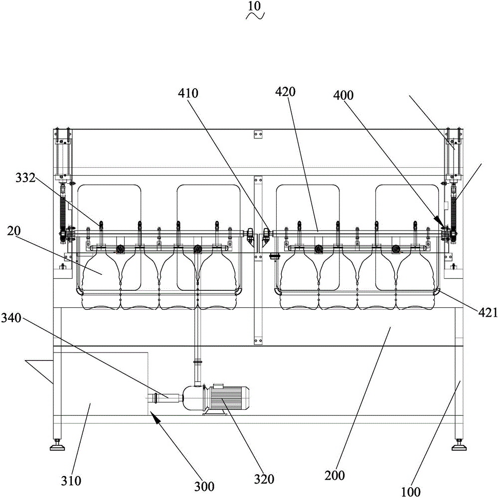
Examples

  • Experimental program(1)

Example Embodiment

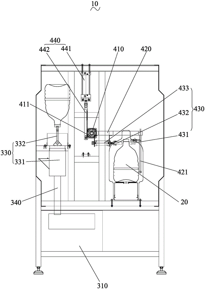
[0021] In order to facilitate the understanding of the present invention, the present invention will be described more fully below with reference to the relevant drawings. The preferred embodiments of the present invention are shown in the drawings. However, the present invention can be implemented in many different forms and is not limited to the embodiments described herein. On the contrary, the purpose of providing these embodiments is to make the disclosure of the present invention more thorough and comprehensive.
[0022] It should be noted that when an element is referred to as being "fixed to" another element, it can be directly on the other element or a central element may also exist. When an element is considered to be "connected" to another element, it can be directly connected to the other element or an intermediate element may be present at the same time. The terms "vertical", "horizontal", "left", "right" and similar expressions used herein are for illustrative purposes only, and are not meant to be the only embodiments.
[0023] Unless otherwise defined, all technical and scientific terms used herein have the same meaning as commonly understood by those skilled in the technical field of the present invention. The terminology used in the specification of the present invention herein is only for the purpose of describing specific embodiments, and is not intended to limit the present invention. The term "and/or" as used herein includes any and all combinations of one or more related listed items.
[0024] Such as figure 1 As shown, a structural diagram of a turning and washing device 10 according to an embodiment of the present invention.
[0025] A reversing and washing device 10 for washing a filling barrel 20, comprising: a work base 100, a conveying device 200 for conveying the filling barrel 20, and a washing device for washing the filling barrel 20 300 and a turning device 400 for turning the filling barrel 20 on the conveying device 200 to the washing device 300 for washing.
[0026] In an embodiment of the present invention, the conveying device 200 is a conveying belt and is arranged under the turning device 400. The filling barrel 20 is transferred to the turning device 400 through a conveyor belt for turning.
[0027] Combine figure 1 versus figure 2 As shown, the turning device 400 includes a rotating rod 410, a turning fixing block 420, a clamping and fixing part 430, and a turning driving part 440. One end of the turning rod 410 is hinged with the work base 100, and the other end is drivingly connected with the turning driving part 440. The fixed block 420 is fixedly installed on the rotating rod 410.
[0028] The turning rod 410 is driven to rotate by the turning driving part 440, thereby driving the turning fixed block 420 installed on the turning rod 410 to turn and turn.
[0029] Such as figure 2 As shown, the clamping fixing part 430 includes: a clamping fixing block 431, a clamping push block 432, and a clamping driving member 433. The clamping fixing block 431 is fixedly installed on the turning fixing block 420, the clamping pushing block 432 and the clamping The driving member 433 is drivingly connected, and the clamping and fixing block 431 and the clamping and pushing block 432 are arranged symmetrically with each other.
[0030] In an implementation of the present invention, the clamping driving member 433 is a clamping driving cylinder.
[0031] It should be noted that after the conveying device 200 conveys the filling barrel 20 in place, the clamping driving member 433 drives the clamping push block 432 to move, so as to cooperate with the clamping fixing block 431 to clamp the filling barrel 20.
[0032] Further, the turning driving part 440 includes a turning driving member 441 and a turning rack 442, the turning driving member 441 is drivingly connected with the turning rack 442, one end of the turning rod 410 is installed with a turning gear 411, and the turning gear 411 meshes with the turning rack 442 .
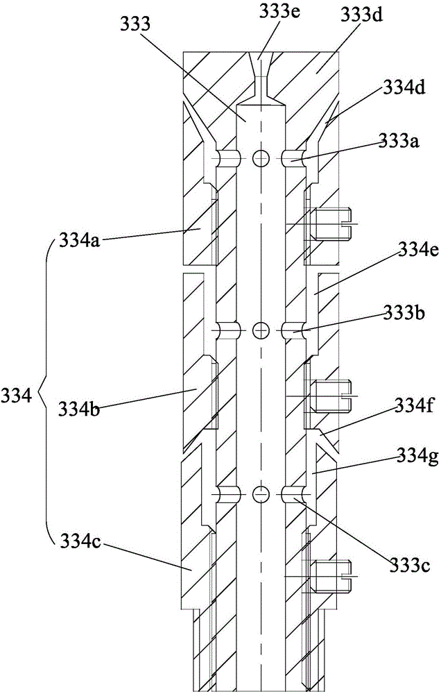
[0033] In an embodiment of the present invention, the turning driving member 441 is a turning driving cylinder, and there are two turning devices 400.
[0034] It should be noted that the rotating rod 410 meshes with the flip rack 442 through the rotating gear 411 provided at one end, so that when the flip driving member 441 drives the flip rack 442 to move, it drives the rotating gear 411 to rotate, so that the rotating rod 410 rotates. The rotating rod 410 drives the turning and fixing block 420 to turn and turn, so that the filling barrel 20 on the clamping and fixing part 430 is turned over to the washing device 300 for washing.
[0035] Further, a limit blocking rod 421 is installed on the side of the turning fixed block 420 away from the rotating rod 410, and the limiting blocking rod 421 and the turning fixed block 420 are arranged perpendicular to each other.
[0036] In an embodiment of the present invention, the limit blocking rod 421 has a "匚"-shaped structure. The limit stop rod 421 acts as a position restriction on the filling barrel 20. On the one hand, the filling barrel 20 can be arranged neatly for transmission during the transmission process of the transmission device 200, and on the other hand, the filling barrel 20 is not turned over. Will deflect each other.
[0037] Combine figure 1 versus figure 2 As shown, the washing device 300 includes: a water storage tank 310, a pumping motor 320, and a washing part 330. The pumping motor 320 is connected to the water storage tank 310 and the washing part 330 through a pipe 340, respectively.
[0038] The washing part 330 includes a washing fixing table 331 and a washing nozzle 332, and the washing nozzle 332 is rotatably installed on the washing fixing table 331. The flushing position of the flushing nozzle 332 can be adjusted by rotating, so that the inside of the filling barrel 20 can be flushed in all directions according to actual conditions.
[0039] Such as image 3 As shown, the flushing nozzle 332 includes a water spray tube 333 and a water spray tube sleeve assembly 334, and the water spray tube 333 is installed in the water spray tube sleeve assembly 334.
[0040] The spray pipe 333 is sequentially provided with a first spray through hole 333a, a second spray through hole 333b, and a third spray through hole 333c, the first spray through hole 333a, the second spray through hole 333b, and the second The three water spray through holes 333c pass through each other, a water spray block 333d is installed on one end of the water spray pipe 333, and the water spray block 333d is provided with a tapered through hole 333e, and the tapered through hole 333e and the water spray pipe 333 pass through each other.
[0041] By providing a tapered through hole 333e on the water spray block 333d, the spraying range of the water outlet end of the water spray pipe 333 is larger, and the effective spray washing can be performed on each position of the bottom of the barrel.
[0042] Further, the water spray pipe sleeve assembly 334 includes: a first water spray pipe sleeve 334a, a second water spray pipe sleeve 334b ​​and a third water spray pipe sleeve 334c, the first water spray pipe sleeve 334a and the first water spray through hole 333a For cooperating installation, the second water spray pipe sleeve 334b ​​is installed in cooperation with the second water spray through hole 333b, and the third water spray pipe sleeve 334c is installed in cooperation with the third water spray through hole 333c.
[0043] In an embodiment of the present invention, one end of the first water spray pipe sleeve 334a close to the first water spray through hole 333a is provided with a first tapered hole 334d, and the other end is in contact with the water spray pipe. The tapered hole 334d is clearance fit.
[0044] It should be noted that the first tapered hole 334d and the water spray block 333d cooperate with each other to form a water outlet hole with a slope. When water is sprayed from the first water spray through hole 333a, it passes through the first water spray pipe sleeve 334a. A tapered hole 334d changes the direction of spraying water, so that the sprayed water has a slope to spray the lower part of the bucket, and the spraying range of the water outlet end is larger, which ensures that all positions of the lower part of the bucket can be effectively sprayed.
[0045] In an embodiment of the present invention, one end of the second water spray pipe sleeve 334b ​​close to the second water spray through hole 333b is provided with a first cylindrical hole 334e, and the other end is provided with a second tapered hole 334f.
[0046] Further, one end of the third water spray pipe sleeve 334c close to the third water spray through hole 333c is provided with a second cylindrical hole 334g, the other end is in contact with the water spray pipe 333, and the second cylindrical hole 334g and the second tapered hole 334f Corresponding cooperation.
[0047] It should be noted that the first cylindrical hole 334e is matched with the bottom of the first spray pipe sleeve 334a so that the water outlet end of the second spray through hole 333b sprays the middle of the barrel horizontally; the second cylindrical hole 334g and the first The two tapered holes 334f correspondingly cooperate to form a water outlet hole with a slope. When water is sprayed from the third water spray through hole 333c, the water spray direction is changed through the second cylindrical hole 334g and the second tapered hole 334f, so that the spray The water has a slope to spray the shoulder of the bucket, and the spraying range of the water outlet is larger to ensure that the lower parts of the bucket can be effectively sprayed.
[0048] Compared with the prior art, the present invention has the following advantages:
[0049] The turning and washing device 10 of the present invention is equipped with a conveying device 200, a washing device 300 and a turning device 400 to realize automatic washing of the filling device 20, thereby greatly improving production efficiency and guaranteed washing quality. The flushing device 400 is set to flip over the flushing device 300 for flushing, so that the flushed water directly flows out of the barrel mouth, thereby bringing the flushed dirt out from the channel together, thereby ensuring the cleanliness of flushing.
[0050] The above-mentioned embodiments only express several embodiments of the present invention, and the descriptions are relatively specific and detailed, but they should not be understood as limiting the scope of the present invention. It should be pointed out that for those of ordinary skill in the art, without departing from the concept of the present invention, several modifications and improvements can be made, and these all fall within the protection scope of the present invention. Therefore, the protection scope of the patent of the present invention should be subject to the appended claims.

PUM

no PUM

Description & Claims & Application Information

We can also present the details of the Description, Claims and Application information to help users get a comprehensive understanding of the technical details of the patent, such as background art, summary of invention, brief description of drawings, description of embodiments, and other original content. On the other hand, users can also determine the specific scope of protection of the technology through the list of claims; as well as understand the changes in the life cycle of the technology with the presentation of the patent timeline. Login to view more.

Similar technology patents

Sensor and method of producing sensor

InactiveUS20070096615A1improve production efficiency
Owner:NGK SPARK PLUG CO LTD

Training scheme generating method and training scheme generating device

PendingCN106251261ACurriculum design is scientificImprove production efficiency
Owner:国家电网有限公司高级培训中心

Classification and recommendation of technical efficacy words

  • Guaranteed cleanliness
  • Improve production efficiency

Highly-efficient cotton fluffer

InactiveCN105040169AGuaranteed cleanlinessEnsure cleanliness
Owner:HENAN XINPUFENG COTTON GIN TECH CO LTD

Dustbin with automatic cleaning function

InactiveCN106742950Aguaranteed cleanlinessreduce the growth of bacteria
Owner:NINGBO JIANGBEI RUICHEN HANDICRAFT DESIGN

Cable winding and unwinding vehicle

PendingCN109911718Aguaranteed cleanlinessImprove unwinding efficiency
Owner:LANG FANG JING LONG GRAND IND MACHINERY CO LTD

Oven for grilling food

Owner:X OVEN INVESTMENTS
Why Eureka
Try Eureka