Automobile brake bottom plate electromagnetic chuck working method

A technology of automobile braking and electromagnetic chuck, which is applied in the direction of manufacturing tools, metal processing equipment, feeding devices, etc., can solve the problems of prone to industrial accidents, unfavorable control of the position of the steel plate and the progress of feeding, and low operating efficiency, so as to improve Effective utilization rate, less accidents at work, and high operating efficiency

Active Publication Date: 2017-02-15
WUHU YUANSHAN MACHINERY MFG CO LTD
View PDF6 Cites 0 Cited by
  • Summary
  • Abstract
  • Description
  • Claims
  • Application Information

AI Technical Summary

Problems solved by technology

[0003] The automobile brake base plate is made of raw materials, usually including blanking, punching, rough forming, finishing and welding. During the blanking process, a whole piece of steel plate is usually used to punch blanking in a stamping machine , in the conventional blanking operation, the steel plate is mainly grasped manually, and the steel plate is sent to the stamping die for stamping and blanking. The operation method of manually grabbing the steel plate and delivering it to the stamping die is not only labor-intensive but also low in efficiency. , In addition, industrial accidents are prone to occur, and the manual operation method is not conducive to accurately controlling the position of the steel plate and the feeding progress, and it is easy to cause waste of steel plate materials; for this reason, it is necessary to provide a working method for the electromagnetic chuck of the automobile brake floor, which can realize Automatic grabbing and feeding actions for steel plate blanking operations to overcome the above problems

Method used


Image

  • Automobile brake bottom plate electromagnetic chuck working method
  • Automobile brake bottom plate electromagnetic chuck working method

Examples


Embodiment Construction

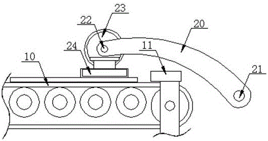
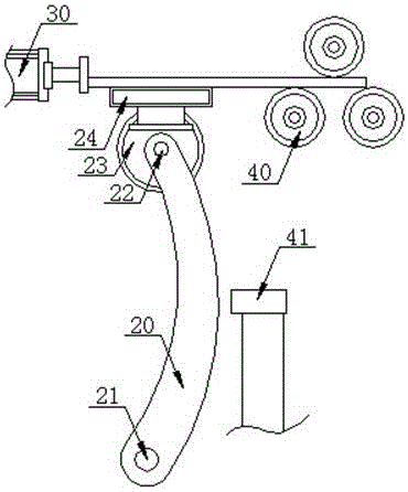
[0017] refer to Figure 1 to Figure 2 , Figure 1 to Figure 2 It is a structural schematic diagram of a specific embodiment of the present invention.

[0018] like Figure 1 to Figure 2 Shown, a kind of automobile brake floor electromagnetic sucker working method, comprises automobile brake floor electromagnetic sucker and comprises sheet metal horizontal conveyer belt 10, rotary pick-up swing arm 20, feeding and pushing cylinder 30, feeding and pushing roller group 40; One end of the rotary fetching swing arm 20 is connected to a rotary drive shaft 21 with a fixed axis position and a rotary drive motor that drives the rotary fetch swing arm 20 to rotate around the rotary drive shaft 21. The other end is provided with an angle adjustment shaft 22, an angle adjustment dial 23 arranged on the angle adjustment shaft 22, an angle adjustment motor for driving the angle adjustment dial 23 to rotate around the angle adjustment shaft 22, and an angle adjustment motor arranged on the...


PUM


Abstract

The invention discloses an automobile brake bottom plate electromagnetic chuck working method. The working method comprises the following steps that an electromagnetic fetching chuck falls freely to the bottom of an angle adjusting turnplate under the action of gravity and is parallel to the horizontal plane, and then a rotary fetching swing arm rotates towards a horizontal plate conveying belt around a rotation driving rotary shaft till the electromagnetic fetching chuck makes contact with a raw steel plate on the horizontal conveying belt; the angle adjusting turnplate is driven to rotate by 180 degrees through an angle adjusting motor; and the rotary fetching swing arm is driven by a rotation driving motor to rotate towards the position between a feeding pushing air cylinder and a feeding pushing roller set, meanwhile, the angle adjusting turnplate is driven by the angle adjusting motor to rotate, the rotation angular speed of the rotary fetching swing arm is made to be identical to that of the angle adjusting turnplate, and the rotation direction of the rotary fetching swing arm is made to be opposite to that of the angle adjusting turnplate. By the adoption of the working method, automatic grabbing and feeding of steel plate blanking operation can be achieved.

Description

technical field [0001] The invention relates to the technical field of mechanical processing equipment, in particular to a working method for an electromagnetic chuck of an automobile brake bottom plate. Background technique [0002] The automobile brake floor is the main force-bearing part of the automobile brake system. The ground braking force of the automobile is transmitted from the brake floor to the axle, so it bears a relatively large load. The automobile brake floor is stamped from a steel plate; the automobile chassis The brake drum is a part of the brake system. When braking, the piston exerts pressure on the two pairs of half-moon brake shoe assemblies to make them stick to the inner wall of the drum, thereby generating friction to stop the rotation of the wheel; the brake bottom plate is The key part of the brake base plate assembly, the brake base plate is the supporting part for the assembly of the fixed brake shoe assembly and the brake drum in the automobile...

Claims


Application Information

Patent Timeline
Patent Type & Authority Applications(China)
IPC IPC(8): B21D43/02B21D43/18B21D43/12B21D43/08B21D28/02
CPCB21D28/02B21D43/02B21D43/08B21D43/12B21D43/18
Inventor 徐杨徐克郎
Owner WUHU YUANSHAN MACHINERY MFG CO LTD
Why Eureka
Try Eureka