Electromagnetic fetching suction cup for machining of automotive brake bottom plate

A technology of automobile brakes and bottom plates, which is applied in the direction of manufacturing tools, metal processing equipment, feeding devices, etc., can solve the problems of low operating efficiency, prone to work-related accidents, and high labor intensity, so as to achieve high operating efficiency and improve effective utilization The effect of low efficiency and labor intensity

Active Publication Date: 2017-03-08
WUHU YUANSHAN MACHINERY MFG CO LTD
View PDF5 Cites 0 Cited by
  • Summary
  • Abstract
  • Description
  • Claims
  • Application Information

AI Technical Summary

Problems solved by technology

[0003] The automobile brake base plate is made of raw materials, usually including blanking, punching, rough forming, finishing and welding. During the blanking process, a whole piece of steel plate is usually used to punch blanking in a stamping machine , in the conventional blanking operation, the steel plate is mainly grasped manually, and the steel plate is sent to the stamping die for stamping and blanking. The operation method of manually grabbing the steel plate and delivering it to the stamping die is not only labor-intensive but also low in efficiency. , In addition, industrial accidents are prone to occur. Again, the manual operation method is not conducive to accurately controlling the position of the steel plate and the progress of feeding, and it is easy to cause waste of steel plate materials. Therefore, it is necessary to design an electromagnetic pick-up sucker for automobile brake floor processing, which can Realize the automatic grabbing and feeding action of steel plate blanking operation to overcome the above problems

Method used


Image

  • Electromagnetic fetching suction cup for machining of automotive brake bottom plate
  • Electromagnetic fetching suction cup for machining of automotive brake bottom plate

Examples


Embodiment Construction

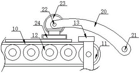
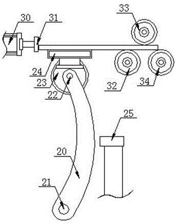
[0015] refer to Figure 1 to Figure 2 , Figure 1 to Figure 2 It is a structural schematic diagram of a specific embodiment of the present invention.

[0016] Such as Figure 1 to Figure 2 As shown, an electromagnetic pick-up sucker for automobile brake bottom plate processing includes a plate horizontal conveyor belt 10, a rotating pick-up manipulator, a feeding and pushing cylinder 30, a feeding and pushing roller group, and is arranged on the plate horizontal conveyor belt 10 for conveying The first proximity switch 13 at the end and the second proximity switch 25 arranged below the feeding and pushing roller group, the rotary pick-up manipulator includes a rotary drive shaft 21, a rotary pick-up shaft arranged on the rotary drive shaft 21 A piece swing arm 20, an angle adjustment turntable 23 arranged on the rotary pick-up swing arm 20, a magnetic pick-up sucker 24 arranged on the angle adjustment turntable 23, one end of the swing pick-up swing arm 20 is connected to th...


PUM


Abstract

The invention discloses an electromagnetic fetching suction cup for machining of an automotive brake bottom plate. The electromagnetic fetching suction cup for machining of the automotive brake bottom plate comprises a plate horizontal-conveying belt, a rotary fetching manipulator, a feeding push air cylinder, a feeding push roller set, a first proximity switch and a second proximity switch. The rotary fetching manipulator comprises a rotary driving shaft, a rotary fetching swing arm, an angle adjustment turnplate and a magnetic fetching suction cup body, wherein one end of the rotary fetching swing arm is fixedly connected with the rotary driving shaft, the angle adjustment turnplate and an angle adjustment motor used for driving the angle adjustment turnplate to rotate are arranged at the other end of the rotary fetching swing arm, and the angle adjustment motor is connected with the angle adjustment turnplate through a rotary angle adjustment shaft; and the magnetic fetching suction cup body is parallel to the axis of the rotary angle adjustment shaft and rotates synchronously along with the angle adjustment turnplate around the rotary angle adjustment shaft. By adoption of the electromagnetic fetching suction cup for machining of the automotive brake bottom plate, automatic grabbing and feeding for steel plate blanking work can be achieved.

Description

technical field [0001] The invention relates to the technical field of mechanical processing equipment, in particular to an electromagnetic pick-up suction cup for processing automobile brake bottom plates. Background technique [0002] The automobile brake floor is the main force-bearing part of the automobile brake system. The ground braking force of the automobile is transmitted from the brake floor to the axle, so it bears a relatively large load. The automobile brake floor is stamped from a steel plate; the automobile chassis The brake drum is a part of the brake system. When braking, the piston exerts pressure on the two pairs of half-moon brake shoe assemblies to make them stick to the inner wall of the drum, thereby generating friction to stop the rotation of the wheel; the brake bottom plate is The key part of the brake base plate assembly, the brake base plate is the supporting part for the assembly of the fixed brake shoe assembly and the brake drum in the automob...

Claims


Application Information

Patent Timeline
Patent Type & Authority Applications(China)
IPC IPC(8): B21D43/18
CPCB21D43/18
Inventor 徐杨徐克郎
Owner WUHU YUANSHAN MACHINERY MFG CO LTD
Why Eureka
Try Eureka