Penetrating hammer grabbing device

A technology for grabbing devices and through-holes, applied in the field of dynamic penetration testing, which can solve the problems of time-consuming and labor-intensive operations, complex overall structure of the penetrating hammer grabbing device, and low degree of automation, so as to achieve high portability and reduce the complexity of the overall structure , the effect of high degree of automation

Pending Publication Date: 2022-06-24
北京市地质机械厂有限责任公司
View PDF9 Cites 0 Cited by
  • Summary
  • Abstract
  • Description
  • Claims
  • Application Information

AI Technical Summary

Problems solved by technology

[0004] This application provides a penetrating hammer grasping device to solve the problems in the prior art that rely on manpower to lift and grasp the heavy hammer, the operation is time-consuming and laborious, the overall structure of the penetrating hammer grasping device is relatively complex, and the degree of automation is low

Method used


Image

  • Penetrating hammer grabbing device
  • Penetrating hammer grabbing device
  • Penetrating hammer grabbing device

Examples


Embodiment 1

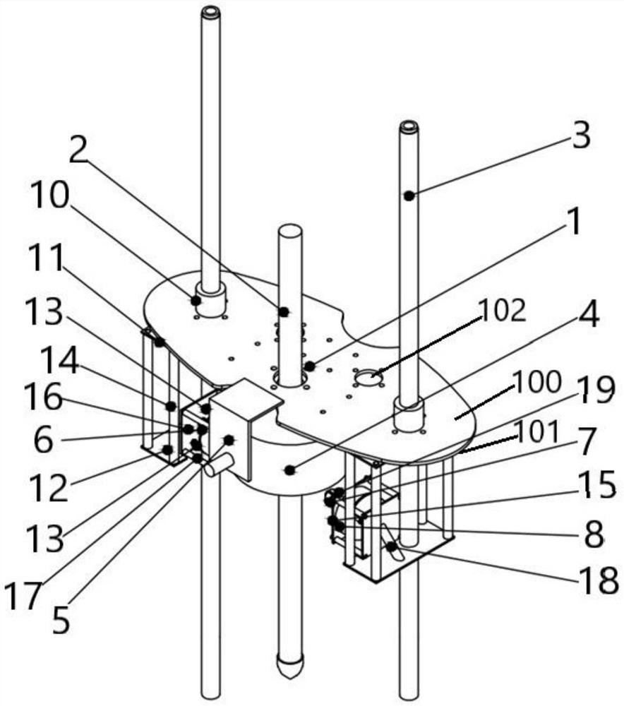
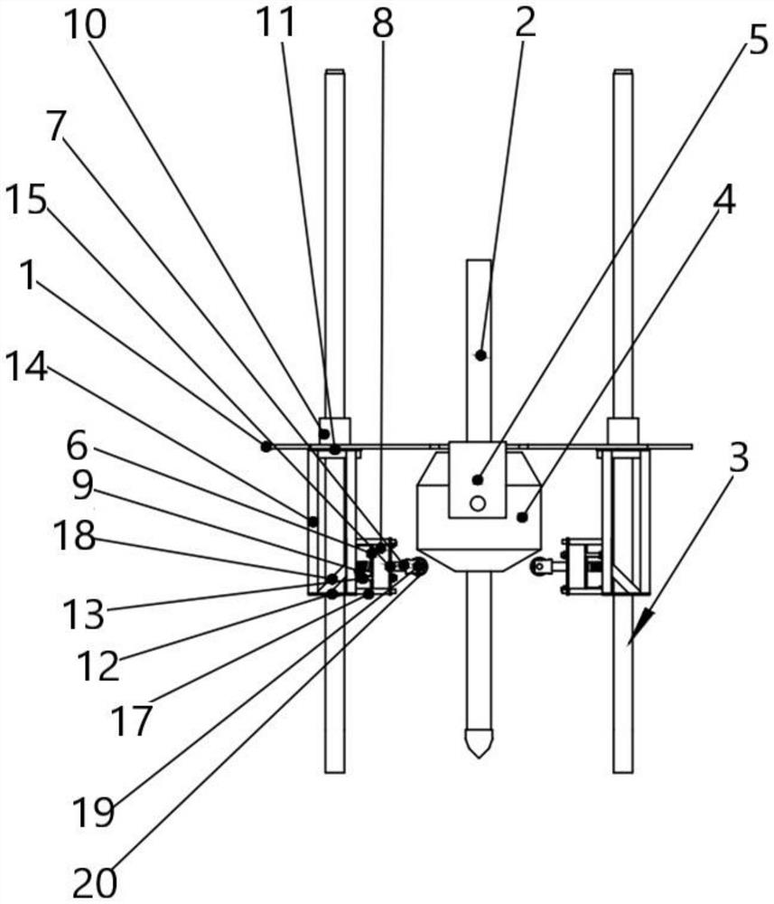
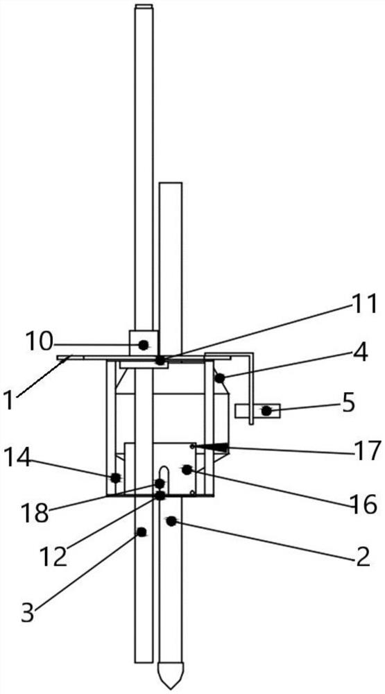
[0048] like Figure 1 to Figure 3 As shown, Embodiment 1 provides a penetrating hammer grabbing device, and the penetrating hammer grabbing device includes:

[0049] Moving platform 1, drill rod 2, guide rail 3, penetration hammer 4, metal sensor 5, sucked plate 6, latch rod 7, electromagnet 8 and spring 9;

[0050] Wherein, two guide rails 3 are symmetrically arranged on both sides of the moving platform 1, and the moving platform 1 is slidably connected with the guide rails 3;

[0051] The drill rod 2 is arranged in the middle of the moving platform 1, and is detachably connected with the penetration hammer 4;

[0052] The metal sensor 5 is fixedly connected to the moving platform 1 for real-time monitoring of the dynamic position of the penetration hammer 4;

[0053] The two sucked plates 6 are symmetrically arranged on both sides of the through hammer 4, and the sucked plates 6 are fixedly connected with the latch rod 7;

[0054] There are two latch rods 7 for lifting t...

Embodiment 2

[0076] The present application provides a terminal device, including a memory, a processor, and a computer program stored in the memory and running on the processor. When the processor executes the computer program, the control mechanism in Embodiment 1 is implemented. steps of a software program.

Embodiment 3

[0078] The present application provides a computer-readable storage medium, where the computer-readable storage medium stores a computer program, and when the computer program is executed by a processor, implements the steps of the software program in the control mechanism of Embodiment 1.

[0079] This application works as follows:

[0080] When the movable platform 1 grabs the penetrating hammer 4, the penetrating hammer 4 is divided into an upper end face and a lower end face, both of which are conical surfaces. At this time, the electromagnet 8 is not energized. 7 moves to the lower end face of the penetrating hammer. At the same time, the moving platform 1 stops moving downward under the control of the metal sensor 5, and uses a mobile power source, namely a battery, to continuously supply power to the electromagnet 8, and the electromagnet 8 absorbs the sucked plate 6. After the electromagnet 8 adsorbs the sucked plate 6 , the metal sensor 5 controls the moving platform ...


PUM


Abstract

The invention provides a penetrating hammer grabbing device. The penetrating hammer grabbing device comprises a movable platform, a drill rod, a guide rail, a penetrating hammer, a metal sensor, an attracted plate, a plug pin rod, an electromagnet and a spring. Two guide rails are symmetrically arranged on the two sides of the movable platform. The drill rod is connected with the penetrating hammer; the metal sensor is connected with the movable platform and used for monitoring the dynamic position of the penetrating hammer. Two sucked plates are symmetrically arranged on the two sides of the penetrating hammer and connected with bolt rods, and the bolt rods are used for lifting the penetrating hammer. The electromagnet is adjacent to the attracted plate, and the electromagnet is used for attracting the attracted plate according to a corresponding instruction so as to fix the bolt rod; the spring is connected with the attracted plate and used for tightly attaching the attracted plate rebounded to the preset position to the electromagnet. The operation of grabbing the penetrating hammer is completed through mutual cooperation of the small electromagnet, the metal sensor, the attracted plate and other main components, and it can be guaranteed that when the attracted plate rebounds to the designated position, the attracted plate and the small electromagnet are tightly attached through cooperation of the bolt rod and the spring.

Description

technical field [0001] The present application relates to the technical field of dynamic penetration, and in particular, to a penetrating hammer grabbing device. Background technique [0002] In the construction process, it is necessary to adopt dynamic penetration technology for foundation pits, etc. The dynamic penetration process mainly relies on the dynamic penetration equipment on the market to realize related operations. The most important part of the dynamic penetration equipment is the penetrating hammer grasping device. [0003] In the prior art, the penetrating hammer grasping device mainly relies on manpower to lift and grasp the heavy hammer. The operation is not only time-consuming and laborious, but also the overall structure of the penetrating hammer grasping device is complex and the degree of automation is low. SUMMARY OF THE INVENTION [0004] The present application provides a penetrating hammer grabbing device to solve the problems in the prior art tha...

Claims


Application Information

Patent Timeline
Patent Type & Authority Applications(China)
IPC IPC(8): B65G47/90
CPCB65G47/901B65G47/905
Inventor 肖振王进卫李劲松郑然刘清晓赵宝忠
Owner 北京市地质机械厂有限责任公司
Why Eureka
Try Eureka