
Electronic element pin forming machine

A technology of electronic components and forming machines, which is applied in the manufacture of contacts, etc., can solve the problems of affecting production efficiency, increasing cost investment, and slow bending speed, etc., and achieves the effects of improving yield rate, compact structure, and convenient feeding

Active Publication Date: 2017-02-15
东莞市捷瑞自动化科技有限公司
View PDF9 Cites 24 Cited by
  • Summary
  • Abstract
  • Description
  • Claims
  • Application Information

AI Technical Summary

Problems solved by technology

In the traditional process, the bending is performed manually with jigs and other tools. The bending speed is slow, which affects the production efficiency, and the labor cost is high, which increases the cost investment. In addition, the shape accuracy of the pin after bending is low and the consistency is poor. , low yield

Method used


Image

  • Electronic element pin forming machine
  • Electronic element pin forming machine
  • Electronic element pin forming machine

Examples


Embodiment Construction

[0027] In order to facilitate the understanding of those skilled in the art, the present invention will be further described below in conjunction with the embodiments and accompanying drawings, and the contents mentioned in the embodiments are not intended to limit the present invention.

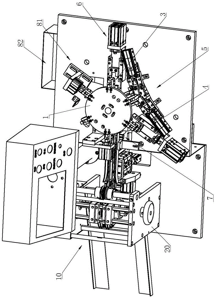
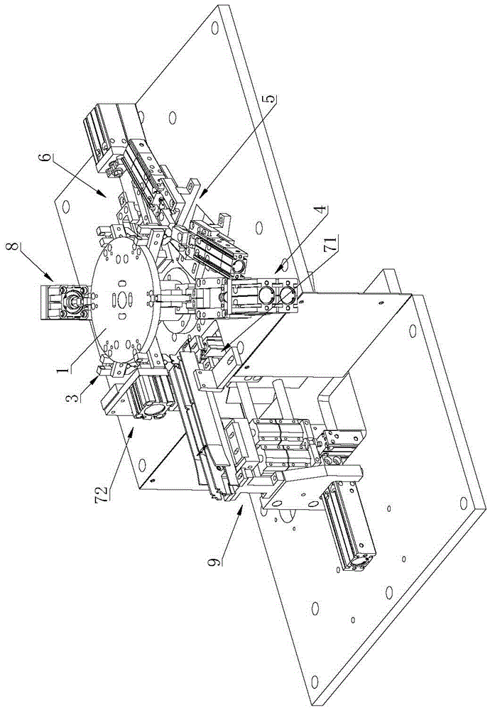
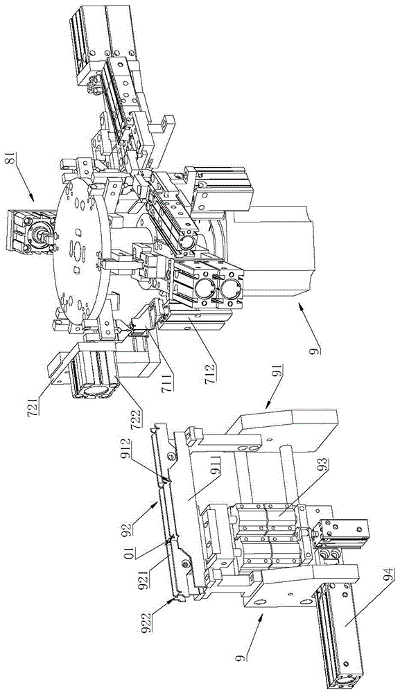
[0028] like Figure 1 to Figure 9 As shown, an electronic component lead forming machine includes a turntable 1, a turntable drive mechanism 2 for driving the turntable 1 to rotate, a number of material clips 3 arranged on the turntable 1, and used for sequentially bending the leads of electronic components. The first bending device 4 and the second bending device 5, the flattening device 6 used to flatten the bent pin, the first bending device 4, the second bending device 5 and the flattening device 6 Set around the turntable 1 in turn.

[0029] In actual application, several material clips 3 are installed on the periphery of the turntable 1, and the number of material clips 3 can be selec...


PUM


Abstract

The invention relates to the technical field of electronic element machining equipment, in particular to an electronic element pin forming machine. The electronic element pin forming machine comprises a turntable, a turntable driving mechanism, multiple clamps arranged on the turntable, a first bending device and a second bending device for bending pins of electronic elements in sequence, and a flattening device for flattening the bent pins. The electronic element pin forming machine is excellent in continuity of conveying and machining of the electronic elements, accelerates the production speed, meanwhile, prevents the clamping error generated by repeated clamping of the electronic elements, and guarantees the forming precision of the pins of the electronic elements. In addition, the electronic element pin forming machine adopts the structure of rotary feeding by the turntable, so that the equipment is compact in structure, less in occupied space and convenient for installation and transportation. After two times of bending are performed for the electronic elements, the flattening is performed, so that the forming is easier to operate, the damage and the resilience after forming of the pins caused by once forming are prevented, and the product yield is improved.

Description

technical field [0001] The invention relates to the technical field of electronic component processing equipment, in particular to an electronic component pin forming machine. Background technique [0002] Electronic components such as capacitors and resistors generally have two pins. In order to meet the needs of connecting with other parts or circuits, sometimes the pins need to be shaped, that is, bent into the desired shape. In the traditional process, the bending is performed manually with jigs and other tools. The bending speed is slow, which affects the production efficiency, and the labor cost is high, which increases the cost investment. In addition, the shape accuracy of the pin after bending is low and the consistency is poor. , The yield rate is low. Contents of the invention [0003] The technical problem to be solved by the invention is to provide an electronic component pin forming machine with compact structure, high forming precision and fast speed. [0...

Claims


Application Information

Patent Timeline
Patent Type & Authority Applications(China)
IPC IPC(8): B21F1/00B21F5/00B21F23/00H01R43/16
CPCB21F1/004B21F5/00B21F23/005H01R43/16
Inventor 王建国
Owner 东莞市捷瑞自动化科技有限公司
Learn More