Friction stir welding (FSW) machine and control method thereof
A friction stir welding machine technology, applied in the control field of friction stir welding machine and friction stir welding machine, can solve problems such as poor control accuracy, and achieve the effect of solving precise control and fast dynamic response speed
- Summary
- Abstract
- Description
- Claims
- Application Information
AI Technical Summary
Problems solved by technology
Method used
Image

Examples
Embodiment 1
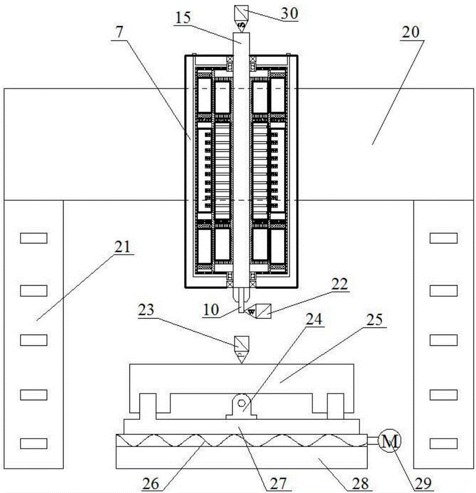
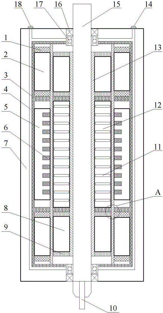
[0033] Embodiment 1: refer to Figure 1-4 , the friction stir welding machine and its displacement and pressure control method of the present invention comprise a stirring head 10, a spindle box 7, a beam 20, a column 21, and a base 28, and the stirring head 10 is installed on the bottom of the stirring shaft 15, and the stirring shaft 15 is two A linear rotary bushing 17 and a thrust bearing 16 are provided at the end; a rotating mover iron core 8 is fixed outside the stirring shaft 15, and a rotating mover winding 9 is arranged at both ends of the rotating mover iron core 8; The sub iron core 8 is correspondingly provided with a rotating stator iron core 2, and the two ends of the rotating stator iron core 2 are provided with a rotating stator winding 1; the stirring shaft 15 is also fixedly provided with a linear mover iron core 12 (secondary iron core), The linear mover iron core 12 is provided with an outer notch, and is embedded with a copper linear mover guide bar 11 (s...
Embodiment 2
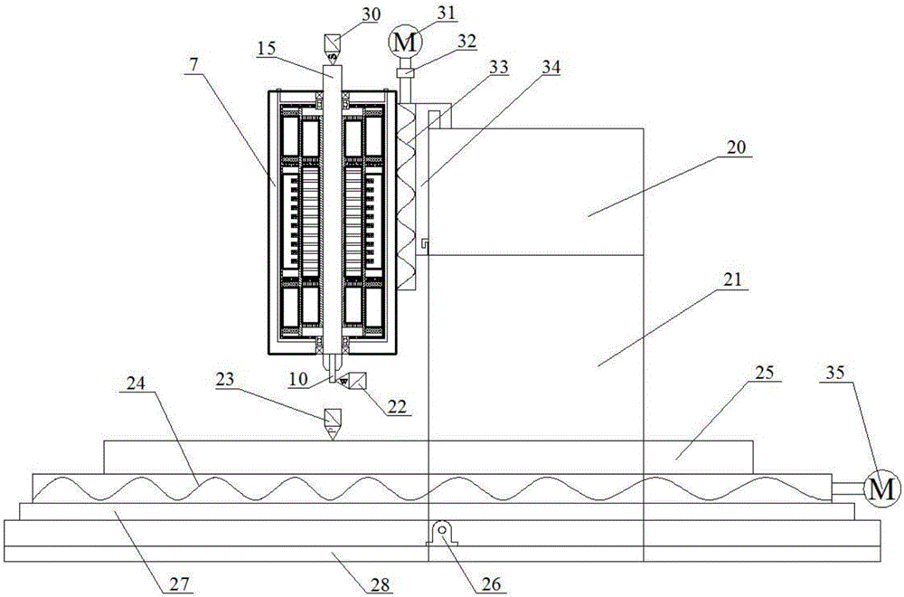
[0046] Embodiment 2: refer to Figure 5 , On the basis of Embodiment 1, the internal structure and control method of the headstock 7 are different, and the rest of the structure and control method are the same. The stirring shaft 15 in the embodiment 1 is divided into a first stirring shaft 43 and a second stirring shaft 44, the first stirring shaft 43 only performs a rotating motion and does not perform an axial linear motion, and the second stirring shaft 44 not only performs a rotating motion but also performs a rotating motion. Axial linear motion. The friction stir welding machine and its displacement and pressure control method of the present invention include a stirring head 10, a spindle box 7, a beam 20, a column 21, and a base 28, and the stirring head 10 is installed on the bottom of the second stirring shaft 44, and the second stirring shaft The upper and lower ends of 44 are provided with linear rotary bushings 17 and thrust bearings 16; the second stirring shaft...
Embodiment 3
[0058] Embodiment 3: refer to Figure 6-9 , the friction stir welding machine and its displacement and pressure control method of the present invention comprise a stirring head 10, a spindle box 7, a beam 20, a column 21, and a base 28, and the stirring head 10 is installed on the bottom of the stirring shaft 15, and the stirring shaft 15 is two A linear rotary bushing 17 and a thrust bearing 16 are provided at the end; a rotating mover iron core 8 is fixed outside the stirring shaft 15, and a rotating mover winding 9 is arranged at both ends of the rotating mover iron core 8; The sub-iron core 8 is correspondingly provided with a rotating stator iron core 2, and the two ends of the rotating stator iron core 2 are provided with a rotating stator winding 1; an air gap 19 is left between the rotating stator iron core 8 and the rotating stator iron core 2; The rotating stator core 2 is provided with a cooling pipe 4, and the two ends of the cooling pipe 4 are connected with a coo...
PUM
 Abstract
Description
Claims
Application Information
 - R&D
- Intellectual Property
- Life Sciences
- Materials
- Tech Scout
- Unparalleled Data Quality
- Higher Quality Content
- 60% Fewer Hallucinations
Browse by: Latest US Patents, China's latest patents, Technical Efficacy Thesaurus, Application Domain, Technology Topic, Popular Technical Reports.
© 2025 PatSnap. All rights reserved.Legal|Privacy policy|Modern Slavery Act Transparency Statement|Sitemap|About US| Contact US: help@patsnap.com