Electric power cable pay-off bracket

A power cable and cable technology, which is applied to the field of power cable pay-off brackets, can solve the problems of affecting the speed of pay-off, easy twisting of cables, etc., and achieve the effects of reducing work intensity, improving work efficiency and simple structure.

Active Publication Date: 2017-02-15
STATE GRID CORP OF CHINA +1
View PDF16 Cites 8 Cited by
  • Summary
  • Abstract
  • Description
  • Claims
  • Application Information

AI Technical Summary

Problems solved by technology

However, when the cable pay-off frame in the prior art is unwound, the cable is easily twisted. When in use, it is often necessary to manually straighten the twisted part of the cable, which greatly affects the speed of unwinding.

Method used


Image

  • Electric power cable pay-off bracket
  • Electric power cable pay-off bracket
  • Electric power cable pay-off bracket

Examples


Embodiment Construction

[0016] In order to make the technical solutions and advantages of the present invention clearer, the technical solutions of the present invention will be clearly and completely described below in conjunction with specific embodiments and accompanying drawings. Obviously, the described embodiments are part of the embodiments of the present invention, and Not all of the embodiments; based on the embodiments of the present invention, all other embodiments obtained by those of ordinary skill in the art without creative efforts fall within the protection scope of the present invention.

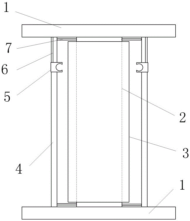
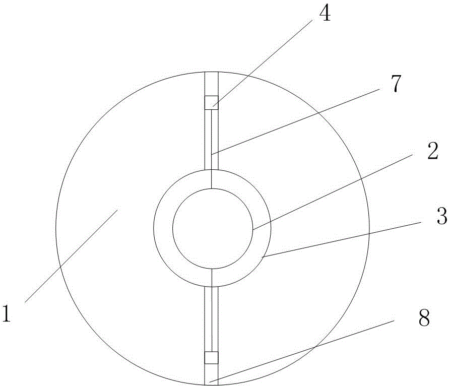
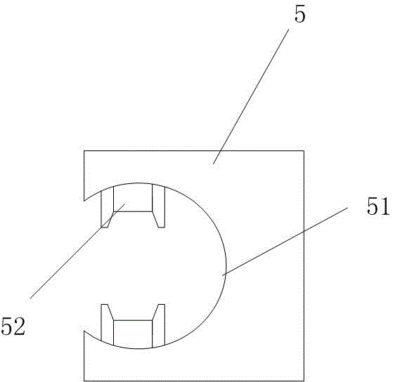
[0017] like Figure 1~3 As shown, the present invention provides a power cable pay-off bracket, which includes two oppositely arranged support plates 1, and the two support plates 1 are connected by a support shaft 2 between them, and the support shaft 2 is externally provided with a A rotating cylinder 3 for winding cables, the rotating cylinder 3 is connected to the support shaft 2 in rotation, a...


PUM


Abstract

The invention provides an electric power cable pay-off bracket. The electric power cable pay-off bracket comprises two oppositely-arranged supporting disks. The two supporting disks are connected through a supporting shaft located between the two supporting disks. A rotating drum used for winding a cable is arranged outside the supporting shaft and rotationally connected with the supporting shaft. At least two limiting rods are arranged outside the rotating drum. The two ends of each limiting rod are slidably arranged on the two supporting disks correspondingly. Each limiting rod is fixedly connected with the supporting shaft through a first elastic component, and thus the limiting rods can move in the direction close to a rotating shaft of the rotating drum. Each limiting rod is provided with a limiting sleeve which can slide in the axial direction of the limiting rod. Each limiting sleeve is provided with a clamping groove used for sleeving the cable. According to the electric power cable pay-off bracket, the structure is simple, using is convenient, and the cable is not prone to being distorted, so that the working intensity of a worker during pulling out of the cable is relieved, and the working efficiency is improved.

Description

technical field [0001] The invention relates to a power cable pay-off bracket and belongs to the technical field of power transmission. Background technique [0002] As power cables are widely used on power supply lines, more and more power cables are laid and repaired. In order to facilitate the storage and transportation of cables, cables are generally wound into coils. Professional reeling equipment or pay-off racks are often required. However, when the cable pay-off frame in the prior art is unwound, the cable is easily twisted. When in use, it is often necessary to manually straighten the twisted part of the cable, which greatly affects the speed of unwinding. Contents of the invention [0003] The invention overcomes the deficiencies in the prior art, and the technical problem to be solved is to provide a power cable pay-off bracket that is convenient for paying out and winding, and is not easy to cause twisting of the cables. [0004] In order to solve the above-m...

Claims


Application Information

Patent Timeline
Patent Type & Authority Applications(China)
IPC IPC(8): B65H49/26
CPCB65H49/26B65H2701/34Y02W30/82
Inventor 张远王鹏宇司磊生宁晋兵许明秦峰柳雪松王涛
Owner STATE GRID CORP OF CHINA
Why Eureka
Try Eureka