
Anaerobic internal circulation reactor

An anaerobic internal circulation and reactor technology, applied in the field of anaerobic reactors, can solve the problems of high sludge content, complex working state of the internal return system, insufficient power of the internal circulation system, etc., and achieve the effect of abundant power

Inactive Publication Date: 2017-02-15
胡明成
View PDF3 Cites 1 Cited by
  • Summary
  • Abstract
  • Description
  • Claims
  • Application Information

AI Technical Summary

Problems solved by technology

[0006] 1. The mixture in the primary reaction zone is prone to clogging during the ascent and descent;
[0007] The working state of the internal return system is very complicated, and the sludge content in the primary reaction zone is very high (generally between 7-12g / l)
In addition, the density of each region in different disturbance states is different, and it is difficult to accurately describe the fluidity of the mud-water mixture
If there is an error in the calculation of the mixture cycle power in the primary reaction zone during the engineering design process, or if there is an error in the calculation of the gas production in the primary reaction zone, the power of the entire internal circulation system will be insufficient, and the elevation design of the internal circulation system will appear. problems, leading to paralysis of the internal circulatory system
[0008] 2. Poor adjustability of the internal circulation system:
[0009] The traditional IC internal circulation system has poor adjustability and cannot adjust its own working conditions according to the actual situation of the treated wastewater

Method used


Image

  • Anaerobic internal circulation reactor
  • Anaerobic internal circulation reactor
  • Anaerobic internal circulation reactor

Examples


Embodiment Construction

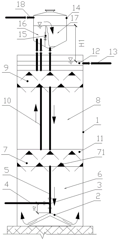
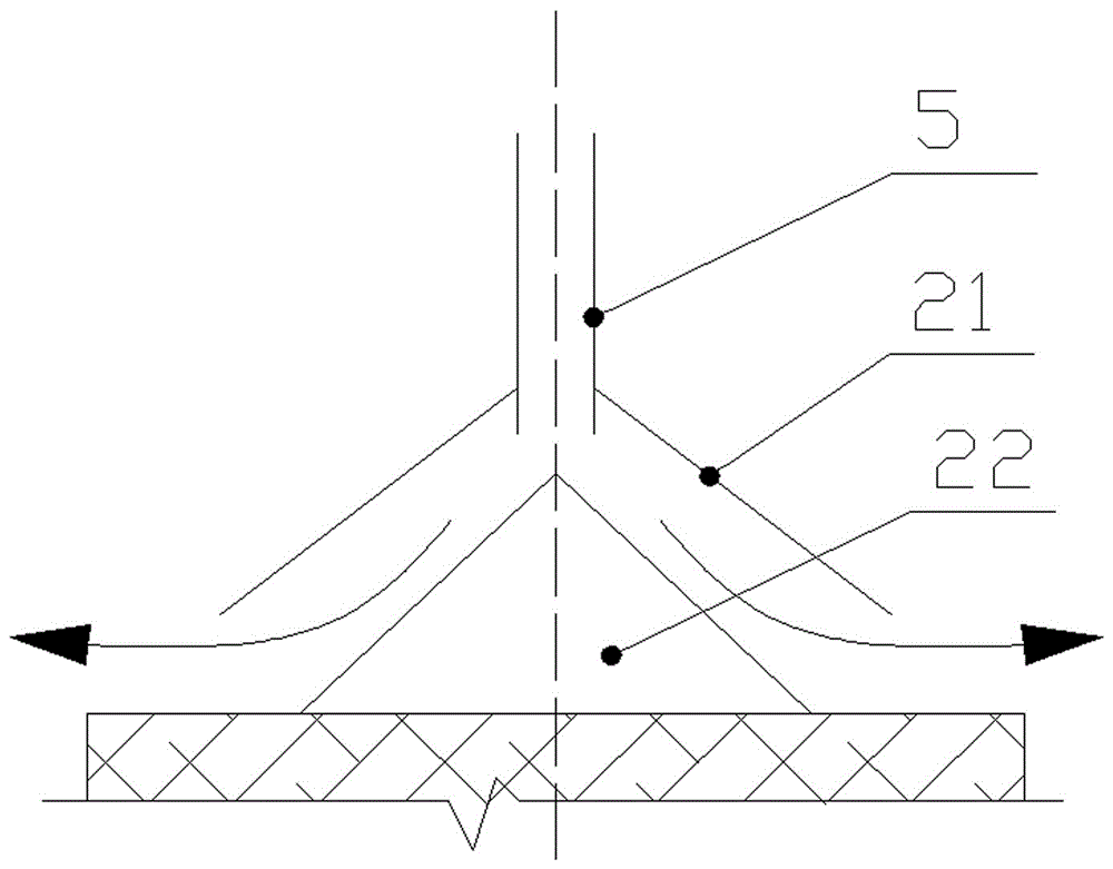
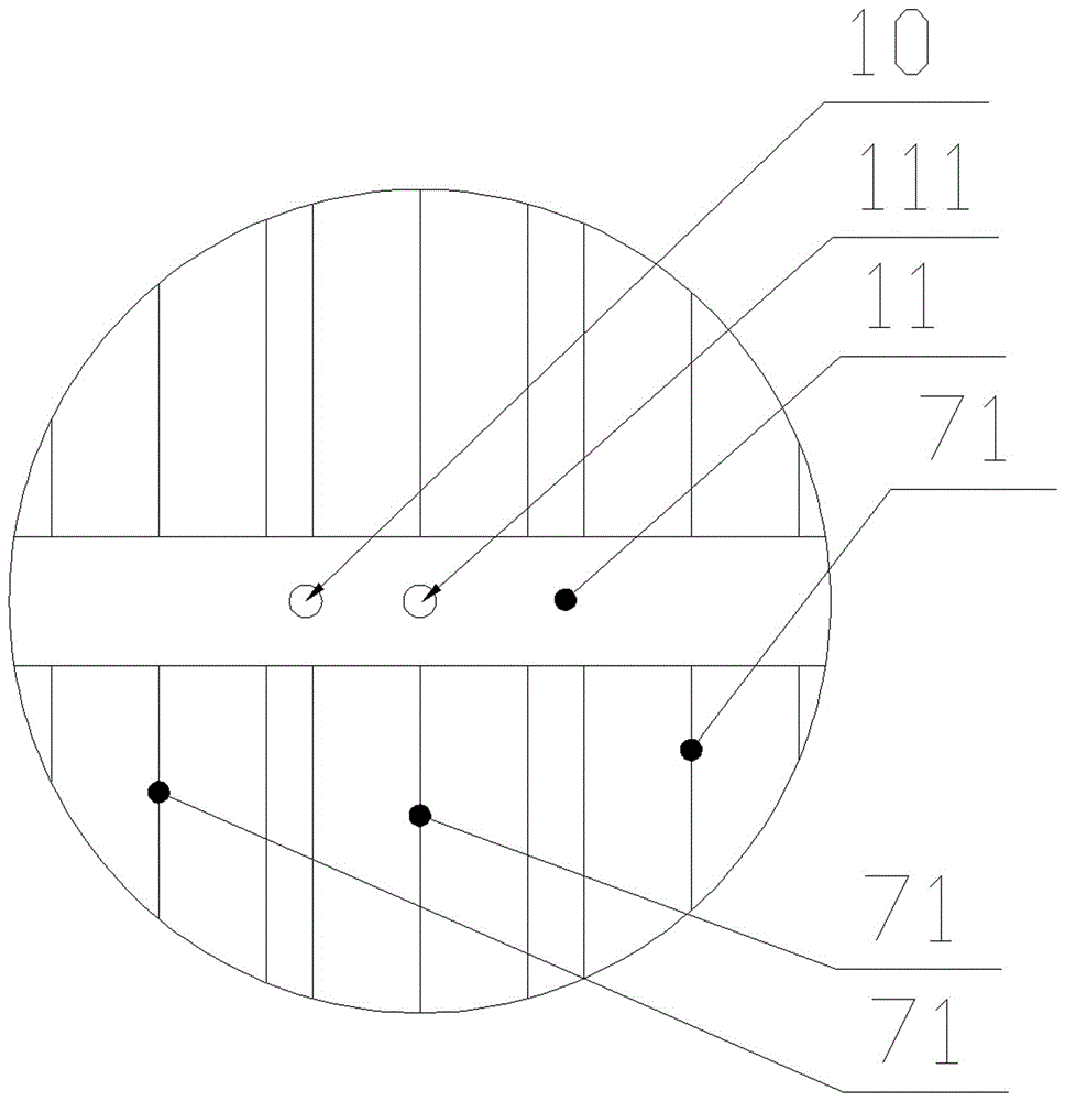
[0031] see Figure 1 to Figure 3, an anaerobic internal circulation reactor, including a reactor cylinder 1 and a gas-water separation box 14 located at the top of the cylinder. A first reaction zone 6 and a second reaction zone 8 are arranged in the reactor cylinder 1 from bottom to top, and the bottom of the reactor cylinder 1 is provided with a water inlet pipe 4 and a flow guiding device 2, and the water inlet pipe 4 It communicates with the upstream end of the flow guide device 2 , and the downstream end of the flow guide device 2 communicates with the first reaction zone 6 in the reactor cylinder 1 . The gas-water separation box 14 is supported on the top of the reactor cylinder 1 by a bracket. The upper part of the gas-water separation box 14 is provided with a biogas outlet for connecting with the biogas pipe 18, and a height-adjustable overflow weir 15 is arranged in the gas-water separation box 14 to separate the gas-water separation box 14 into mixed Liquid rising...


PUM


Abstract

The invention relates to an anaerobic internal circulation reactor. The anaerobic internal circulation reactor comprises a reactor barrel and a gas-water separating box positioned at the top end of the barrel. A first reaction region and a second reaction region are arranged in the reactor barrel from bottom to top. A flow guide device is arranged at the bottom of the first reaction region, an upstream end of the flow guide device communicates with a water feeding tube and a downcomer, and a downstream end of the flow guide device communicates with the first reaction region in the reactor barrel. The gas-water separating box at the top end of the reactor barrel is divided into a mixed liquid ascending region and a mixed liquid descending region by a height-adjustable overflow weir plate; the bottom of the mixed liquid descending region communicates with the upstream end of the flow guide device through the downcomer; and the mixed liquid ascending region of the gas-water separating box is respectively connected with a gas collecting groove ascending tube of a first three-phase separator on the upper part of the first reaction region and a gas collecting groove ascending tube of a second three-phase separator on the upper part of the second reaction region. An internal circulation system is good in adjustability, and the reactor is high in running stability.

Description

technical field [0001] The invention relates to an anaerobic reactor, in particular to an anaerobic internal circulation reactor. Background technique [0002] From a macroscopic point of view, the IC (Internal Iirculation) anaerobic reactor is a completely mixed anaerobic reactor (first-stage reaction zone) and an anaerobic reactor (secondary reaction zone) working in a plug-flow state along the longitudinal direction. A compound reactor formed by working in series. Because the IC reactor makes full use of the characteristics of the strong shock load resistance of the complete mixing reactor and the good water quality of the plug flow reactor, this anaerobic reactor has a very broad application prospect. [0003] However, this reactor also has disadvantages. One is that the internal structure of IC reactor is more complicated than that of ordinary anaerobic reactor, so the requirements for design and installation are very high. The second is that this kind of reactor has...

Claims


Application Information

Patent Timeline
IPC IPC(8): C02F3/28
CPCC02F3/286C02F3/2873C02F2203/006Y02E50/30
Inventor 胡明成
Owner 胡明成
Learn More