A production structure for multi-reservoir commingled production

A multi-oil layer and oil pipe technology, which is applied in the development of fluids, earth-moving drilling, drilling pipes, etc., can solve the problems of insignificant economic benefits of single-branch multi-layer oil well production, inability to achieve co-production with existing production processes, and complicated processes. The effect of improving mining efficiency, simplifying complex processes and reducing mining costs

Inactive Publication Date: 2019-03-19
CHINA UNIV OF PETROLEUM (EAST CHINA)
View PDF6 Cites 2 Cited by
  • Summary
  • Abstract
  • Description
  • Claims
  • Application Information

AI Technical Summary

Problems solved by technology

[0002] In the process of reservoir exploration, some superimposed oil layers are often involved. Due to the different pressures of each oil layer, if the single-layer well production technology is used, it will often cause problems of compatibility between oil layers, such as oil production flow problems, etc., and gradually The process of layer-by-layer oil recovery is cumbersome, time-consuming and labor-intensive, and the economic benefits of layer-by-layer extraction are not significant for single multi-layer oil wells. In order to solve the above problems, the co-production technology is generally used for single The known co-production technology is usually only used for the partial pressure co-production of two oil layers or the co-production of multiple oil layers at the same pressure, but some superimposed oil layers have three or more different pressure oil layers, making it impossible to achieve co-production with the existing production technology

Method used


Image

  • A production structure for multi-reservoir commingled production
  • A production structure for multi-reservoir commingled production
  • A production structure for multi-reservoir commingled production

Examples


Embodiment Construction

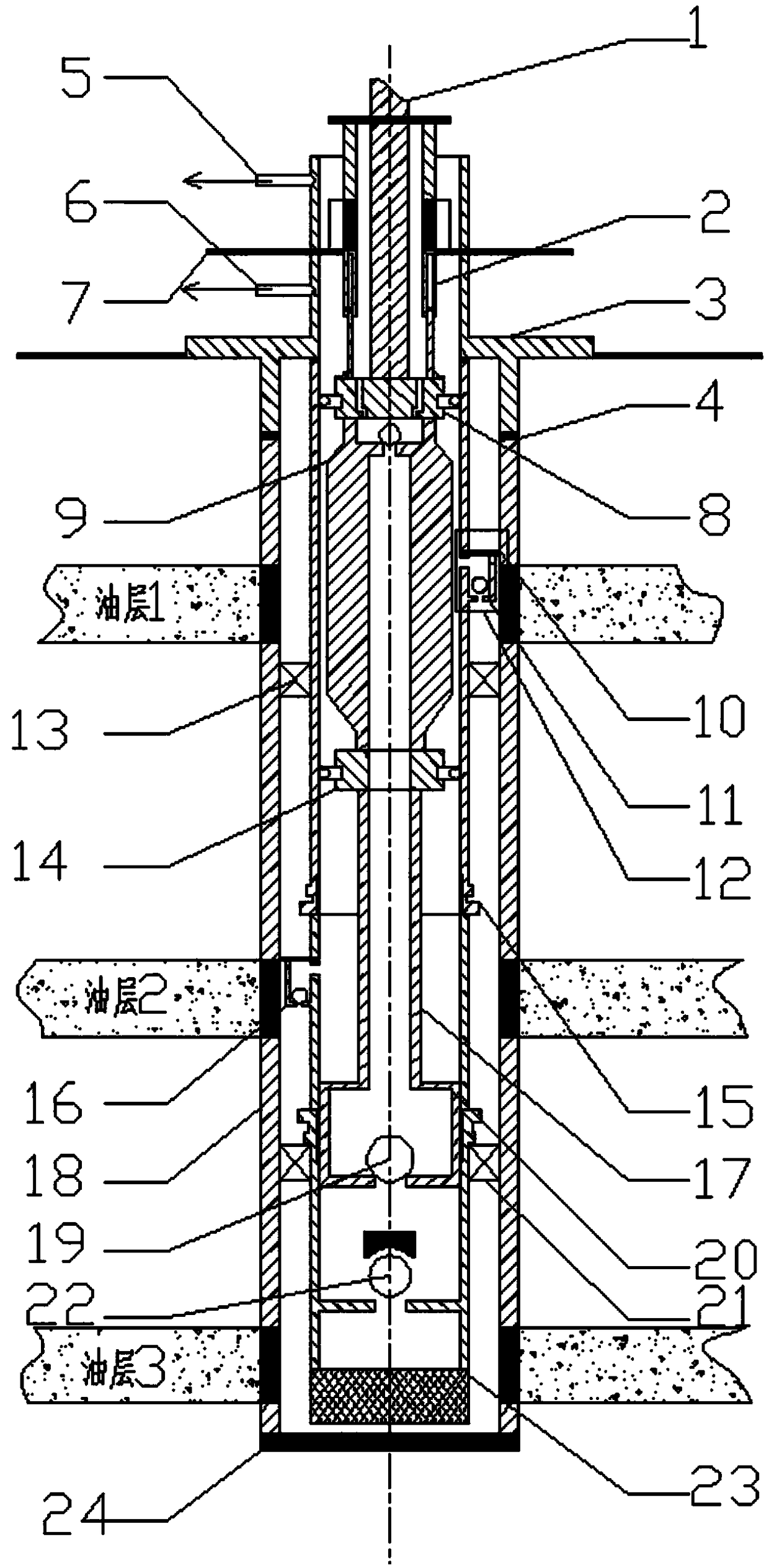
[0021] Below in conjunction with accompanying drawing and example, the present invention will be further described:

[0022] like figure 1 As shown, an oil production structure for commingled production of multiple oil layers comprises a polished rod (1), a plunger-type annular partition (2), a casing head (3), a threaded sealing ring (4), and an upper liquid outlet (5) , lower liquid outlet (6), oil and gas separator (7), overflow centralizer (8), convex annular pipe (9), sealing ring (10), valve ball (11), upper side valve (12) ), upper packer (13), hollow centralizer (14), oil pipe (15), lower side valve (16), hollow sucker rod (17), casing (18), swimming valve (19) , pump barrel (20), lower packer (21), fixed valve (22), screen pipe (23), bottom hole (24), the polished rod (1) passes through the flow centralizer (8) and The convex annular pipe (9) is connected, the polished rod (1) is connected to the ground device to transmit power, the upper liquid outlet (5), the lowe...


PUM


Abstract

The invention relates to an oil production structure capable of achieving multi-oil-layer commingled production. The oil production structure comprises a polished rod, a plunger type annular partition plate, a casing head and the like. The polished rod is connected with a reversed-T-shaped annulus pipe through an overflow centralizer. An upper liquid outlet, a lower liquid outlet and an oil-gas partition plate are all connected with the casing head. The plunger type annular partition plate is connected with the oil-gas partition plate and the centralizer. The reversed-T-shaped annulus pipe is connected with a hollow sucker rod through a hollow centralizer. The hollow sucker rod is connected with a pump cylinder. The pump cylinder is connected with a fixing valve. The casing head is connected with a sleeve through a threaded seal ring. The sleeve is connected with a shaft bottom. The casing head is connected with an oil pipe. The oil pipe is connected with a screen pipe through the fixing valve. An upper side valve, an upper packer, a lower side valve and a lower packer are each connected with the oil pipe and the sleeve. The upper side valve comprises a seal ring and a valve ball. The oil production structure has the beneficial effects that the oil production structure can be used for three-layer commingled production with different pressures, the oil field oil production efficiency is improved, the production process is simplified, the production cost of oil fields is reduced, and the economic benefits of single-support multi-layer oil well production are improved.

Description

Technical field [0001] The invention relates to an oil production pipe string structure for commingled production of multiple oil layers, in particular to an oil production structure system for commingled production of three oil layers with different pressures in the same wellbore at the same time. technical background [0002] In the process of oil reservoir exploration, some superimposed oil layers are often involved. Due to the different pressures of each oil layer, if the single-layer well production technology is used, it will often cause problems of co-production compatibility between oil layers, such as the problem of oil production and flow. The process of layer-by-layer oil production is cumbersome, time-consuming and labor-intensive, and the economic benefits of layer-by-layer production for single multi-layer oil wells are not significant. The known co-production technology is often only used for the partial pressure co-production of two oil layers or the co-produ...

Claims


Application Information

Patent Timeline
Patent Type & Authority Patents(China)
IPC IPC(8): E21B43/14E21B17/10
CPCE21B17/10E21B17/1071E21B43/14
Inventor 綦耀光张晧杨勇潘隆毛正义潘婷姚尧朱森贾文强
Owner CHINA UNIV OF PETROLEUM (EAST CHINA)
Why Eureka
Try Eureka