An intelligent installation device for large mining height hydraulic support and its application
A technology for hydraulic support and installation equipment, applied in mining equipment, mine roof support, earthwork drilling and other directions, can solve the problems of complex installation equipment structure, cumbersome installation process, low installation accuracy and installation efficiency, etc.
- Summary
- Abstract
- Description
- Claims
- Application Information
AI Technical Summary
Problems solved by technology
Method used
Image
Examples
Embodiment 1
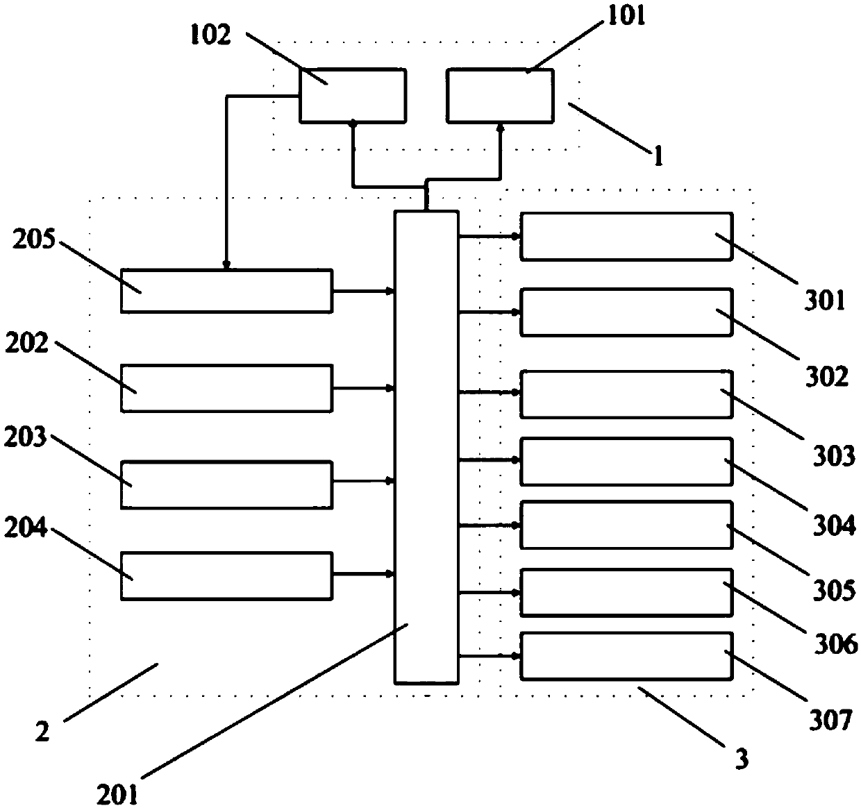
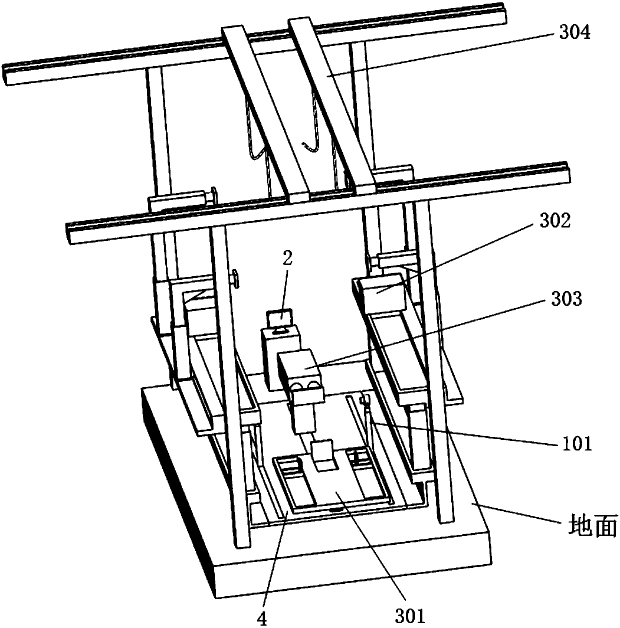
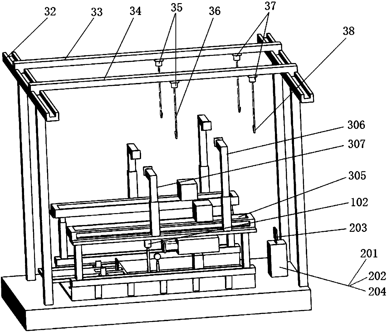
[0072] like Figure 1 to Figure 6b As shown, this embodiment provides an intelligent installation device for large mining height hydraulic supports, including installation execution system 3, pin shaft hole positioning assembly 1 and control system 2, control system 2, installation execution system 3, and pin shaft hole positioning assembly 1 The electrical connection is used for the operation of the intelligent control installation execution system 3 and the pin hole positioning component 1;
[0073] The installation execution system 3 includes a mobile platform assembly 301, a lifting device 304, a clamping device, and a manipulator assembly; the mobile platform assembly 301 is used to move the base of the hydraulic support to the target position, and the lifting device 304 is used to move the hydraulic support front link, rear link The pole, top beam and cover beam are moved to the target position, and the manipulator assembly is used to grab the pin and complete the instal...
Embodiment 2
[0085] An intelligent installation device for a hydraulic support with a large mining height, the structure of which is as described in Embodiment 1, the difference is that the intelligent installation device for a hydraulic support with a large mining height also includes a rear connecting rod pushing cylinder assembly 303, and a rear connecting rod pushing cylinder assembly 303 Including cylinder base 16, pushing plate 17, pushing oil cylinder, pushing cylinder base 19 and lifting cylinder base 20, the bottom end of cylinder base 16 is slidingly arranged in the middle chute, lifting cylinder base 20 is set in cylinder base 16, lifting cylinder The top of seat 20 connects and pushes away cylinder block 19, and pushes away cylinder block 19 and is provided with and pushes away oil cylinder, and the piston rod 18 of pushing away oil cylinder passes and moves behind cylinder block 19 and is hinged with pushing plate 17. The rear connecting rod push cylinder assembly can move forw...
Embodiment 3
[0087] An operation method for assembling hydraulic supports using the intelligent installation equipment for large mining height hydraulic supports described in Embodiment 2, comprising the following steps,
[0088] (1) First, connect the cover beam ZJ4, the front connecting rod ZJ3 and the rear connecting rod ZJ2 of the hydraulic support to form an assembly for standby; install the column on the base of the hydraulic support for standby;
[0089] (2) Turn on the intelligent installation equipment of large mining height hydraulic support, the reference coordinate system is determined by the control system 2, the intelligent installation equipment is in the initial position, that is, the mobile platform assembly 301 is located at the forefront of the middle chute, and the laser light assembly 101 is located in the right chute The front end of the projection board assembly 102 is located at the front end of the left chute. At this time, the initial position coordinates of the co...
PUM
 Abstract
Description
Claims
Application Information
 - R&D
- Intellectual Property
- Life Sciences
- Materials
- Tech Scout
- Unparalleled Data Quality
- Higher Quality Content
- 60% Fewer Hallucinations
Browse by: Latest US Patents, China's latest patents, Technical Efficacy Thesaurus, Application Domain, Technology Topic, Popular Technical Reports.
© 2025 PatSnap. All rights reserved.Legal|Privacy policy|Modern Slavery Act Transparency Statement|Sitemap|About US| Contact US: help@patsnap.com


