Disperse air film cooling hole structure

A technology of air film cooling and cooling holes, which is applied to the supporting elements of blades, engine elements, machines/engines, etc., to achieve the effect of expanding the outlet width, enhancing the adhesion ability of the air film, and having a high cooling effect.

Inactive Publication Date: 2017-02-15
INST OF ENGINEERING THERMOPHYSICS - CHINESE ACAD OF SCI
View PDF5 Cites 18 Cited by
  • Summary
  • Abstract
  • Description
  • Claims
  • Application Information

AI Technical Summary

Problems solved by technology

However, from the perspective of cooling effect, the film cooling effect of the continuous groove structure is obviously better than that of various cooling holes based on discretized cylindrical holes, but due to some problems in the manufacture, structure, and layout of the continuous groove, It limits its use on turbine cooling blades, but the basic structure of the groove structure can be used for reference to develop a more efficient cooling hole structure

Method used


Image

  • Disperse air film cooling hole structure
  • Disperse air film cooling hole structure
  • Disperse air film cooling hole structure

Examples


Embodiment Construction

[0037] In order to make the object, technical solution and advantages of the present invention clearer, the present invention will be further described in detail below in conjunction with specific embodiments and with reference to the accompanying drawings.

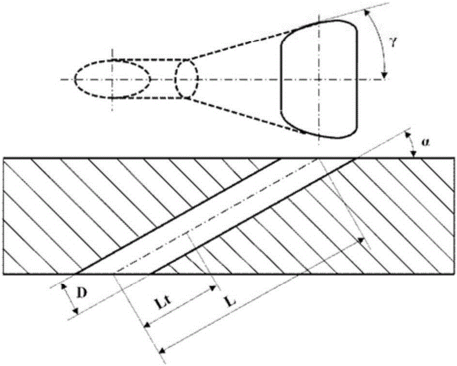
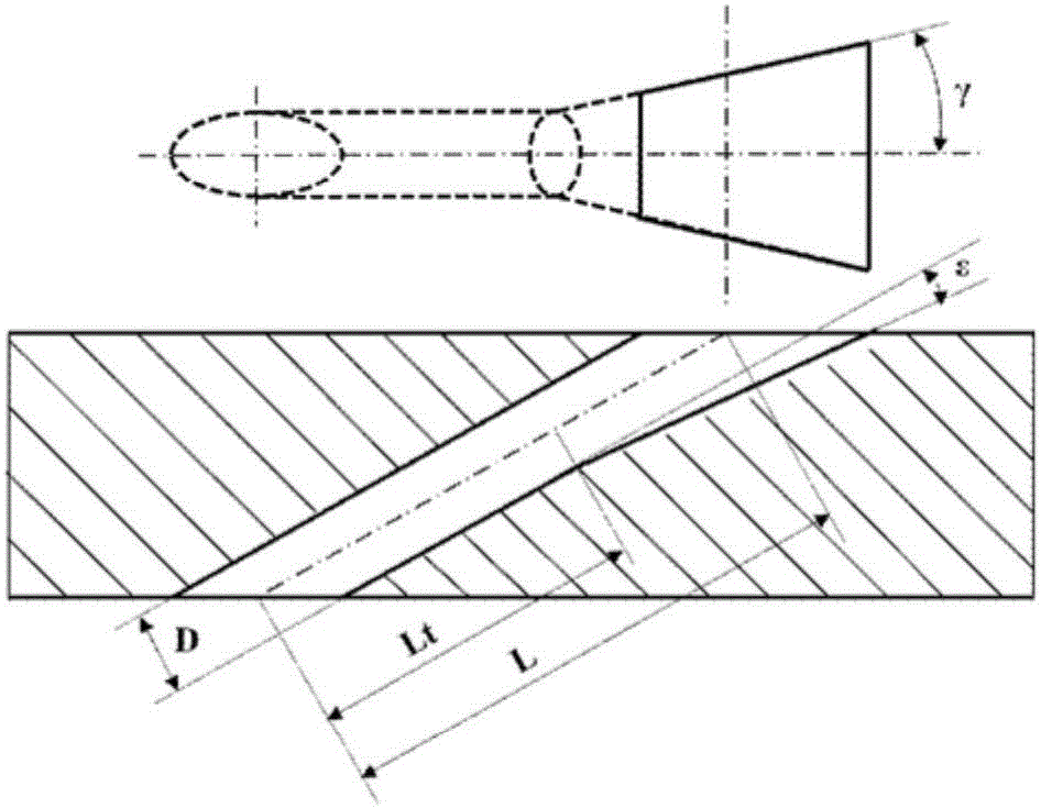
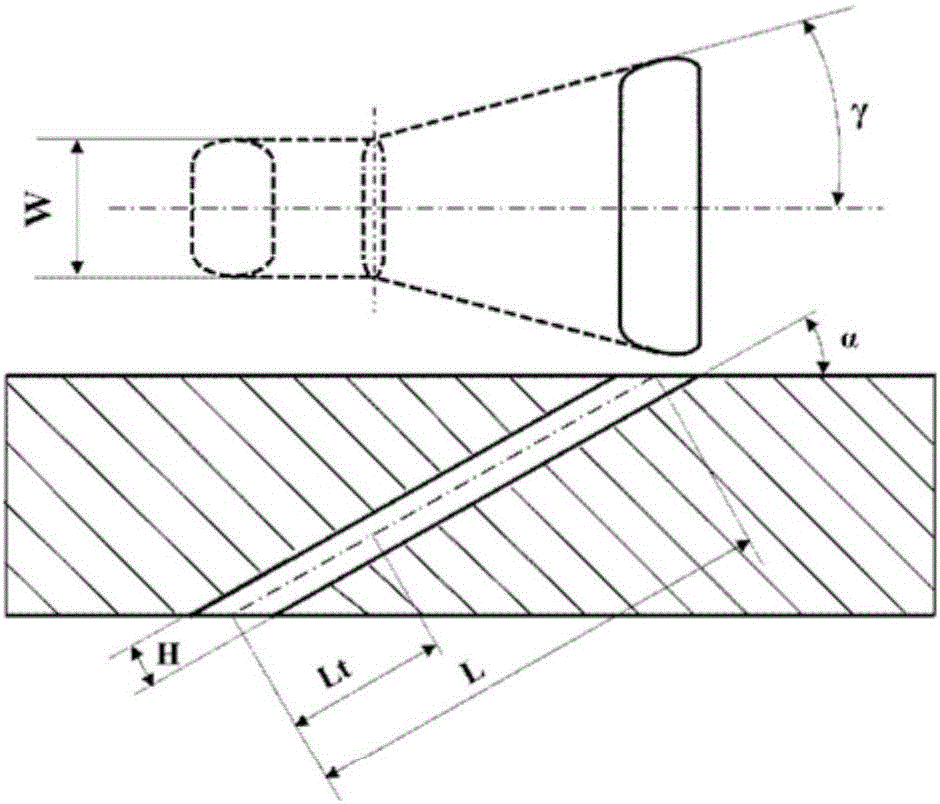
[0038] Figure 1a and Figure 1b The structures of the existing fan-shaped and dustpan-shaped expansion holes are respectively shown, which are the two most widely used cooling holes at present, and the cooling effect of the simple cylindrical hole is greatly improved. Both holes are expansion holes, that is, the first half of the cooling hole is a cylindrical hole, and the second half of the cooling hole is an expansion structure, including lateral expansion and front expansion. The length of the straight section of the hole is represented by Lt, the total length of the hole is represented by L, the lateral expansion angle is represented by γ, and the front expansion angle is represented by ε. Apparently, the two existi...


PUM


Abstract

The invention discloses a disperse air film cooling hole structure which is used for air film cooling of bodies or upper edge plates and lower edge plates of turbine blades of a gas turbine. A cooling hole is overall of the expansion structure and is divided into a straight section and an expansion section in the cold air flow direction; the straight section is located on the cold air side; and the expansion section is located on the gas side. The cross section profile of the straight section is a flat rectangle, and each of short edges at the two sides of the flat rectangle has an inwards-contracting structure. The disperse air film cooling hole has the advantages that an air film is large in transverse width and uniform in covering, and the air film cooling effect is good; a stable reverse-kidney-shaped vortex pair is formed at the downstream position, and the air film is not prone to being separated from the wall face under a high blowing ratio; the cold air outlet velocity is high, and the pneumatic mixing loss is small; and the disperse air film cooling hole is simple in structure and can be easily achieved in actual turbine cooling blades.

Description

technical field [0001] The invention relates to the technical field of gas turbines, and is a structure of discrete air film cooling holes, which can greatly improve the air film cooling effect and lateral air film coverage area of ​​gas turbine blades, and at the same time, the mixing loss is not large, and is suitable for use in gas turbine blade passages Surfaces that require cooling. Background technique [0002] Gas turbines are widely used in aviation, military, transportation, electric power and other fields. In order to improve the thermal efficiency of the whole machine, the turbine inlet temperature of gas turbines is getting higher and higher. At present, it has far exceeded the temperature resistance limit of turbine blade alloy materials. Discrete hole film cooling is currently the most commonly used high-efficiency cooling technology, and is widely used in gas turbine blade airfoil and edge plate cooling. The basic principle is to introduce cooling air from th...

Claims


Application Information

Patent Timeline
Patent Type & Authority Applications(China)
IPC IPC(8): F01D5/18
CPCF01D5/186F05D2260/202
Inventor 安柏涛刘建军
Owner INST OF ENGINEERING THERMOPHYSICS - CHINESE ACAD OF SCI
Why Eureka
Try Eureka