High-power hybrid braking expander

A hybrid brake and expander technology, which is applied in the direction of engine components, machines/engines, mechanical equipment, etc., can solve problems such as the inability to use booster brake expanders, etc., to achieve a wide range of applications, meet the needs of large-load operation, Ease of use

Active Publication Date: 2017-02-15
CHINA OIL BLUE OCEAN PETROLEUM TECH
View PDF7 Cites 2 Cited by
  • Summary
  • Abstract
  • Description
  • Claims
  • Application Information

AI Technical Summary

Problems solved by technology

[0005] The technical problem to be solved by the present invention is to provide a high-power expander that can better meet the demand for large-load operation at the expansion end when the process design of the low-temperature device cannot use the booster braking mode expander and requires high-power braking effect. Hybrid Brake Expander

Method used


Image

  • High-power hybrid braking expander
  • High-power hybrid braking expander
  • High-power hybrid braking expander

Examples


Embodiment

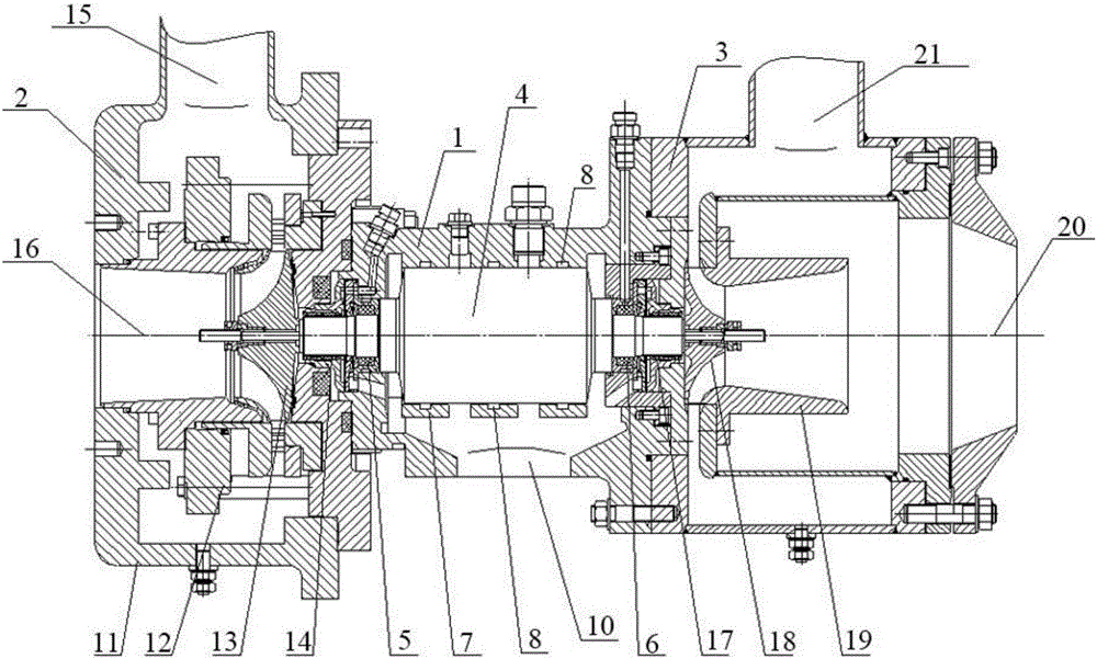
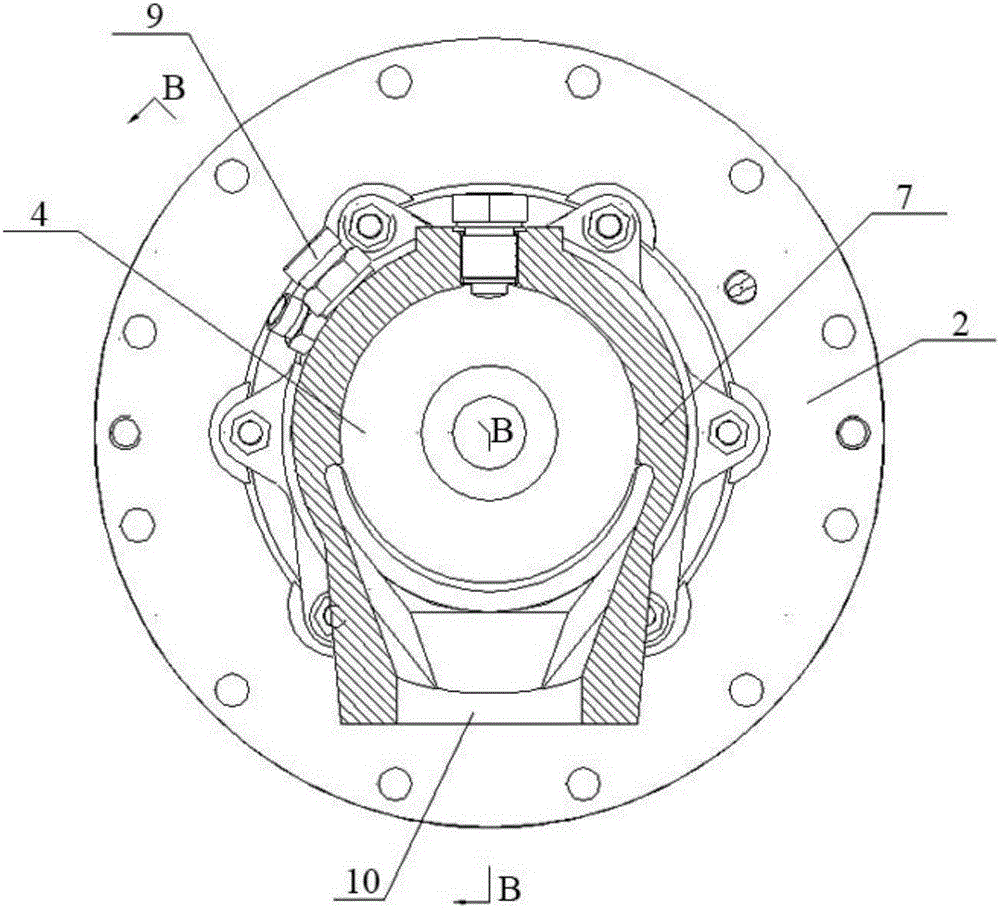
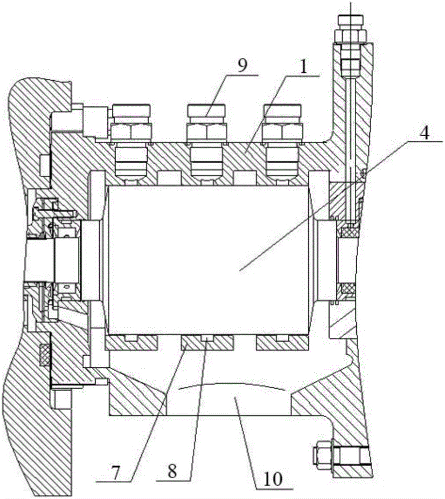
[0038] Such as Figure 1 to Figure 5 As shown, a high-power hybrid braking expander includes an expander main shaft 1 and an expansion end 2 and a fan brake end 3 coaxially arranged at both ends of the expander main shaft 1. The expander main shaft 1 includes a main shaft 4 and the main shaft casing surrounding the main shaft 4, the two ends of the main shaft 4 are axially connected to the two ends of the main shaft casing through the expansion end bearing 5 and the braking end bearing 6 respectively, and are respectively connected with The expansion end 2 and the brake end 3 of the fan are transmission-connected, and an expansion end shaft seal 14 for sealing is preferably arranged between the expansion end bearing 5 and the expansion end 2, and the brake end bearing 6 Preferably, a brake end shaft seal 17 for sealing is arranged between the fan brake end 3;

[0039] Wherein, the expansion end 2 may include an expander volute 11, an expansion impeller 13, and an adjustable n...


PUM


Abstract

The invention relates to a high-power hybrid braking expander. The high-power hybrid braking expander comprises an expander spindle, an expansion end and a fan braking end. The expander spindle comprises a spindle and a spindle housing. The two ends of the spindle are correspondingly and rotationally connected with the two ends of the spindle housing through bearings and are correspondingly connected with the expansion end and the fan braking end in a transmission manner. The expander spindle is provided with at least one spindle oil brake. Each spindle oil brake comprises an annular braking body and a braking body oil inlet pipeline. The spindle is rotationally connected with the annular braking bodies. An annular braking oil groove communicating with the corresponding braking body oil inlet pipeline is formed in the inner ring wall of each annular braking body. An oil supply and return opening is formed in the spindle housing. Compared with the prior art, according to the high-power hybrid braking expander, the spindle oil brakes and the fan braking end are utilized comprehensively for braking; and when by means of a low-temperature device process design, a pressurizing braking expander cannot be used and the high-power braking effect is needed, the requirement of the expansion end on the large load operation can be well met, and the braking power can reach 200 kw and can be adjusted according to the actual operation load of the expansion end.

Description

technical field [0001] The invention relates to the field of turbo expanders, in particular to an expander in a non-supercharging braking mode. Background technique [0002] The turbo expander is an effective machine to achieve a near-adiabatic isentropic expansion process. The gas working medium obtains a low temperature during the expansion process and at the same time works externally. Therefore, the application of the expander includes two functions: obtaining low-temperature cooling capacity and recovering energy. (External work); no matter what kind of expander, the other end of the coaxial shaft needs a braking end, which absorbs the work output by the expander and controls the operating speed of the expander at the same time. [0003] At present, the braking end of the turbo expander includes a turbo compressor (supercharger), a generator, an oil brake, a fan brake, etc. Generally, in order to make full use of energy, a turbo compressor is used as the braking end, th...

Claims


Application Information

Patent Timeline
Patent Type & Authority Applications(China)
IPC IPC(8): F01D21/00F01D15/08
CPCF01D15/08F01D21/006F05D2260/901F05D2260/904
Inventor 丁俊郝群
Owner CHINA OIL BLUE OCEAN PETROLEUM TECH
Why Eureka
Try Eureka