Special speed reducer for hub motor

A technology of in-wheel motor and reducer, applied in mechanical equipment, gear transmission, belt/chain/gear, etc., can solve the problems of inability to bear axial load, high production efficiency and high cost, and achieve easy modular production and installation. Fast and firm, reducing production costs

Inactive Publication Date: 2017-02-15
宁波东力股份有限公司
View PDF5 Cites 1 Cited by
  • Summary
  • Abstract
  • Description
  • Claims
  • Application Information

AI Technical Summary

Problems solved by technology

Although some in-wheel motors have solved the problem of small output torque by setting reducers, some reducers and in-wheel motors are integrated, which is not conducive to the modular production of reducers, high cost and low efficiency, and most reducers are compatible with The connection of the outer hub is unreasonable, resulting in the problem that the output moment arm is too small and the later installation is inconvenient, and it cannot bear a larger axial load
[0004] To sum up, the current hub reducers on the market have the problems of high production efficiency, low cost, large output torque, fast installation, and ability to withstand large axial loads.

Method used


Image

  • Special speed reducer for hub motor
  • Special speed reducer for hub motor
  • Special speed reducer for hub motor

Examples


Embodiment Construction

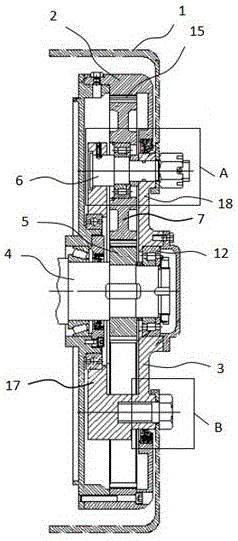
[0023] In order to make it easy to understand the technical means, creative features, goals and effects achieved by the present invention, the following examples are combined with the appended figure 1 to attach image 3 The technical solutions provided by the present invention are described in detail, but the following content is not intended as a limitation of the present invention.

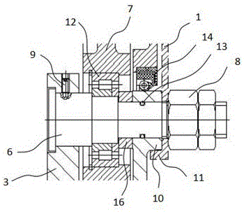
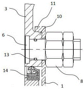
[0024] figure 1 It is a structural diagram of an embodiment of a special reducer for in-wheel motors of the present invention; figure 2 for figure 1 Enlarged view of part A in the middle; image 3 for figure 1 Enlarged view of part B in . Such as figure 1 with figure 2 As shown, the in-wheel motor-specific reducer provided in this embodiment includes: outer hub 1, frame 2, bracket 3, upper layer 18, lower layer 17, input shaft 4, sun gear 5, bearing 12, planetary shaft 6, positioning pin 9, Planetary gear 7, shaft sleeve 16, internal ring gear 15, sealing ring 13, sealing structure 14...


PUM


Abstract

The invention provides a special speed reducer for a hub motor and belongs to the technical field of speed reducers. The special speed reducer for the hub motor comprises an outer hub, a bracket, a planetary mechanism, an input shaft and a frame. The frame is arranged in the outer hub. The input shaft is arranged in the middle of the frame and is sleeved with the bracket through a bearing. The planetary mechanism is arranged between the input shaft and the frame. The input shaft is sleeved with a sun gear. A planetary shaft is fixedly arranged on the bracket and sleeved with a planetary gear. An independent unit is arranged to facilitate later modular production, and the production cost is lowered. A spigot is arranged on the bracket. The spigot has the taper. The spigot is matched with a spigot matching position of the outer hub and is connected with the planetary shaft through a compression nut. Torque is output through the planetary shaft, so that the output torque is larger. As the spigot and the spigot matching position both have the tapers, and the two tapers are matched with each other, so that locating is more accurate, mounting is faster and firmer, and higher axial load can be borne.

Description

technical field [0001] The invention relates to the technical field of speed reducers, in particular to a special speed reducer for hub motors. Background technique [0002] In recent years, with the development of the automobile industry and the strengthening of people's awareness of environmental protection, people hope to manufacture transportation tools with low energy consumption, low emission, and non-traditional energy consumption. Therefore, electric vehicles at home and abroad have emerged as the times require. [0003] Electric vehicles are more efficient, quieter and produce fewer emissions than conventional vehicles powered by internal combustion engines. As the vanguard of sustainable industrial development and new energy development, the electric vehicle industry is already an inevitable trend in the future development of the automotive industry. However, due to the technical defects of the existing electric vehicles, the manufactured products are difficult to...

Claims


Application Information

Patent Timeline
Patent Type & Authority Applications(China)
IPC IPC(8): F16H1/28F16H57/021F16H57/023F16H57/027F16H57/029F16H57/02
CPCF16H1/28F16H57/02F16H57/021F16H57/023F16H57/027F16H57/029F16H2700/00
Inventor 蔡汉龙费新路周升杉
Owner 宁波东力股份有限公司
Why Eureka
Try Eureka