Micro accelerator and manufacturing method thereof

A technology of micro-accelerometer and cover plate, which is applied in the direction of measuring acceleration, velocity/acceleration/impact measurement, and measuring devices, etc. It can solve the problems of micro-accelerometer measurement result drift, cantilever beam occupying too much space, and size is not large enough, etc. Achieve the effects of small temperature effect, small detection modal stiffness and high sensitivity

Inactive Publication Date: 2017-02-15
PEKING UNIV SHENZHEN GRADUATE SCHOOL
View PDF12 Cites 8 Cited by
  • Summary
  • Abstract
  • Description
  • Claims
  • Application Information

AI Technical Summary

Problems solved by technology

The size of the existing micro-accelerometer is not large enough, and the cantilever beam takes up too much space, the measurement results of the micro-accelerometer drift seriously, are greatly affected by external factors such as temperature, have low sensitivity, and poor overall performance

Method used


Image

  • Micro accelerator and manufacturing method thereof
  • Micro accelerator and manufacturing method thereof
  • Micro accelerator and manufacturing method thereof

Examples


Embodiment Construction

[0016] The following will be further described in detail through specific embodiments in conjunction with the accompanying drawings.

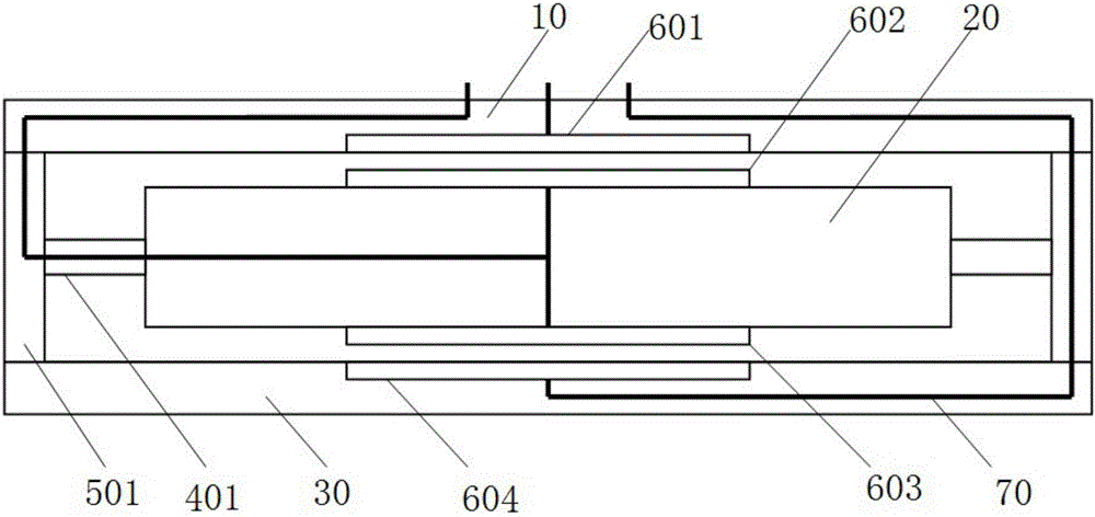
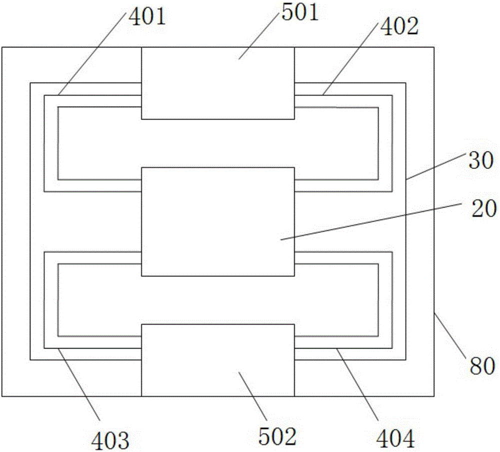
[0017] Such as figure 1 with figure 2 As shown, the present embodiment discloses a micro accelerometer, which mainly includes an upper cover plate 10, a mass block 20, a lower cover plate 30, a first cantilever beam 401, a second cantilever beam 402, a third cantilever beam 403, a Four cantilever beams 404 , a first surrounding frame 501 , a second surrounding frame 502 , and a housing 80 .

[0018] The upper cover 10 is opposite to the lower cover 30 to form a space.

[0019] The first surrounding frame 501 is opposite to the second surrounding frame 502 for supporting the upper cover 10 and the lower cover 30 . One end of the first surrounding frame 501 is connected to the edge of the lower surface of the upper cover plate 10, and the other end is connected to the edge of the upper surface of the lower cover plate 30. Here, the lower surf...


PUM


Abstract

The present invention discloses a micro accelerator. The device comprises an upper cover plate, a mass block, a lower cover plate, a cantilever beam and an enclosure frame. The upper cover plate and the lower cover plate are oppositely arranged to form a space, one end of the enclosure frame is connected with the lower surface of the upper cover plate, and the other end of the enclosure frame is connected with the upper surface of the lower cover plate; the mass block is connected with the enclosure frame though the cantilever beam and is arranged in the space formed by the upper cover plate and the lower cover plate; and the cantilever beam has a bending shape and is configured to support the mass block to move up and down in the space formed by the upper cover plate and the lower cover plate. The present invention further discloses the manufacturing method of the micro accelerator. The method comprises curtain coating, punching and through-hole filling, alignment, lamination, cofiring, assembling and detection, etc. The LTCC difference capacitive micro accelerator has the cantilever beam which has a bending shape such as a U-shaped structure, and is simple in preparation; and moreover, the micro accelerator is low in measurement result drifting, small in temperature effect and high in sensitivity, small in detection modal stiffness, small in cross coupling and good in combination property.

Description

technical field [0001] The present application relates to the field of micro-accelerometers, in particular to a differential capacitive micro-accelerometer and a manufacturing method thereof. Background technique [0002] Due to the advantages of small size, light weight, high measurement accuracy, low price per piece, and convenience for large-scale mass production, micro-accelerometers are widely used in military and civilian fields, and have broad market prospects and research value. The size of the existing micro-accelerometer is not large enough, and the cantilever beam takes up too much space, the measurement results of the micro-accelerometer drift seriously, are greatly affected by external factors such as temperature, have low sensitivity, and poor overall performance. Contents of the invention [0003] According to one aspect of the present invention, a micro accelerometer is provided, which includes an upper cover plate, a mass block, a lower cover plate, a cant...

Claims


Application Information

Patent Timeline
Patent Type & Authority Applications(China)
IPC IPC(8): G01P15/125
CPCG01P15/125
Inventor 覃明杰缪旻金玉丰
Owner PEKING UNIV SHENZHEN GRADUATE SCHOOL
Why Eureka
Try Eureka