Sealant curing method and liquid crystal panel manufacturing method

A liquid crystal panel and curing method technology, applied in nonlinear optics, instruments, optics, etc., can solve the problems of reduced curing rate of sealant, human skin damage, low curing rate of visible light sealant, etc. Effect of cure rate

Inactive Publication Date: 2017-02-15
TCL CHINA STAR OPTOELECTRONICS TECH CO LTD
View PDF9 Cites 6 Cited by
  • Summary
  • Abstract
  • Description
  • Claims
  • Application Information

AI Technical Summary

Problems solved by technology

As the irradiated area of ​​ultraviolet light decreases, the curing rate of ultraviolet light to frame glue decreases
In addition, ultraviolet light can cause damage to human skin, and ultraviolet light can oxidize oxygen into ozone, causing damage to the environment
[0003] The existing technology proposes to use visible light greater than 400nm to cure the frame glue, and has developed a visible light sealant, but only uses a 400nm filter to filter out the ultraviolet light less than 400nm, and does not have the most suitable visible light waveband for the sealant Conduct research that results in lower cure rates for visible light sealants

Method used


Image

  • Sealant curing method and liquid crystal panel manufacturing method
  • Sealant curing method and liquid crystal panel manufacturing method
  • Sealant curing method and liquid crystal panel manufacturing method

Examples


Embodiment 1

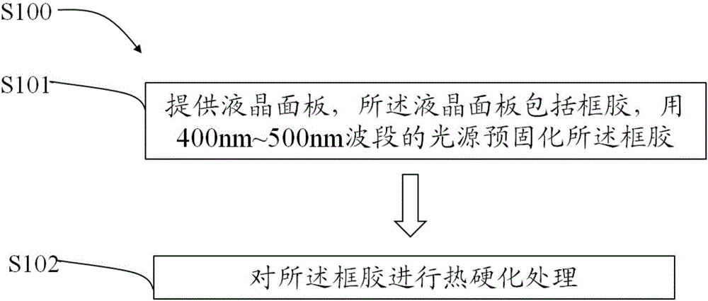
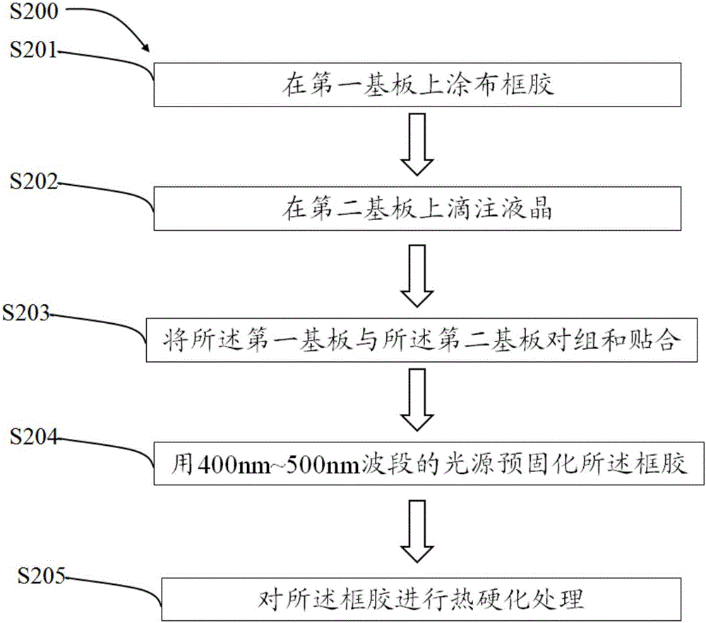
[0042] Provide a liquid crystal panel, the liquid crystal panel includes a frame glue, use an ultraviolet light filter to filter the ultraviolet light and visible light below 430nm in the visible light lamp in the 380-800nm ​​band, and obtain the visible light in the 430-800nm ​​band, and use the above-mentioned visible light to comprehensively carry out the liquid crystal panel The irradiation, the visible light intensity is 120mW / cm 2 , After a curing time of 30 to 100 seconds. The curing rate of the frame glue of the liquid crystal panel in this embodiment was tested after photocuring, and the curing rate of the liquid crystal panel was less than 30%.

Embodiment 2

[0044] A liquid crystal panel is provided, the liquid crystal panel includes frame glue, ultraviolet light and visible light below 400nm in a visible light lamp in the 380-800nm ​​band are filtered by an ultraviolet filter, and visible light above 500nm is filtered by an optical filter to obtain a light in the 400-500nm band Visible light, and the light intensity is concentrated in the 420-500nm band, using the above visible light to fully irradiate the liquid crystal panel, the visible light intensity is 120mW / cm 2 , After a curing time of 30 to 100 seconds. The curing rate of the sealant of the liquid crystal panel in this embodiment was tested after light curing, and the curing rate of the liquid crystal panel was 46%.

Embodiment 3

[0046] A liquid crystal panel is provided, the liquid crystal panel includes frame glue, ultraviolet light and visible light below 400nm in visible light lamps with a wavelength of 380 to 800nm ​​are filtered by an ultraviolet filter, and visible light above 450nm is filtered by an optical filter to obtain light in a wavelength range of 400 to 450nm Visible light, and the light intensity is concentrated in the 400-430nm band, using the above visible light to fully irradiate the liquid crystal panel, the visible light intensity is 120mW / cm 2 , After a curing time of 30 to 100 seconds. The curing rate of the sealant of the liquid crystal panel in this embodiment was tested after photocuring, and the curing rate of the liquid crystal panel was 51%.


PUM

PropertyMeasurementUnit
strengthaaaaaaaaaa
strengthaaaaaaaaaa
strengthaaaaaaaaaa

Abstract

The invention provides a sealant curing method. The method includes the steps that a liquid crystal panel with sealant is provided, visible light with the wave band of 400-500 nm can irradiate the liquid crystal panel, and accordingly the sealant is cured; the sealant is subjected to thermal hardening. A liquid crystal panel manufacturing method includes the steps that a first substrate is coated with the sealant; liquid crystals are dripped on a second substrate; the first substrate and the second substrate are paired and attached; a light source with the wave band of 400-500 nm is used for pre-curing the sealant; the sealant is subjected to thermal hardening. The optimal visible light sealing wave band is disclosed by analyzing and researching the visible light wave band, and accordingly the sealant curing rate is increased.

Description

technical field [0001] The invention relates to the field of liquid crystal panel manufacturing, in particular to a frame glue curing method and a liquid crystal panel manufacturing method. Background technique [0002] With the development of narrow frame technology, it is more and more difficult to make and align UV light shields during the process of UV curing frame glue. As the irradiated area of ​​the ultraviolet light decreases, the curing rate of the frame glue by the ultraviolet light decreases. In addition, ultraviolet light can cause damage to human skin, and ultraviolet light can oxidize oxygen into ozone, causing damage to the environment. [0003] The existing technology proposes to use visible light greater than 400nm to cure the frame glue, and has developed a visible light sealant, but only uses a 400nm filter to filter out the ultraviolet light less than 400nm, and does not have the most suitable visible light waveband for the sealant Studies were conducte...

Claims


Application Information

Patent Timeline
Patent Type & Authority Applications(China)
IPC IPC(8): G02F1/1339G02F1/1333
CPCG02F1/1339G02F1/1333
Inventor 张勇李定良
Owner TCL CHINA STAR OPTOELECTRONICS TECH CO LTD
Why Eureka
Try Eureka