Dust collector fan linkage control circuit
A technology of linkage control and dust collector, applied in the field of separation, can solve the problems of wasting air source, reducing dust collection efficiency, reducing the service life of filter parts, etc., to ensure the service life, avoid wasting air source, and eliminate potential safety hazards.
- Summary
- Abstract
- Description
- Claims
- Application Information
AI Technical Summary
Problems solved by technology
Method used
Image
Examples
Embodiment 1
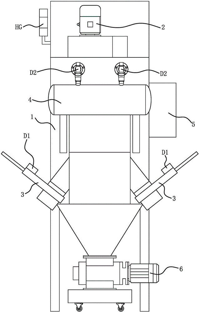
[0022] Such as figure 1 As shown, the dust collector includes a dust removal box 1 with a dust removal chamber and a fan 2 with a motor, and a filter element is installed in the dust removal chamber. There are two air inlets on the dust removal box 1, each air inlet is provided with a pneumatic valve 3, and each pneumatic valve 3 is controlled by a first electromagnetic valve D1. An air storage tank 4 is fixed on the outer wall of the dust removal box 1, and a back-blowing air pipe is pierced in the filter element, and the air storage tank 4 and the back-blowing air pipe are connected through a second electromagnetic valve D2.
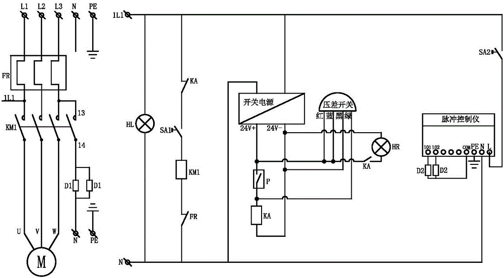
[0023] Such as figure 2 As shown, the dust collector fan linkage control circuit includes motor comprehensive protector FR, AC contactor KM1, switching power supply and pulse controller.
[0024] The motor comprehensive protector FR is used for the overload and phase failure protection of the motor in the fan 2. The model of motor comprehensive pro...
Embodiment 2
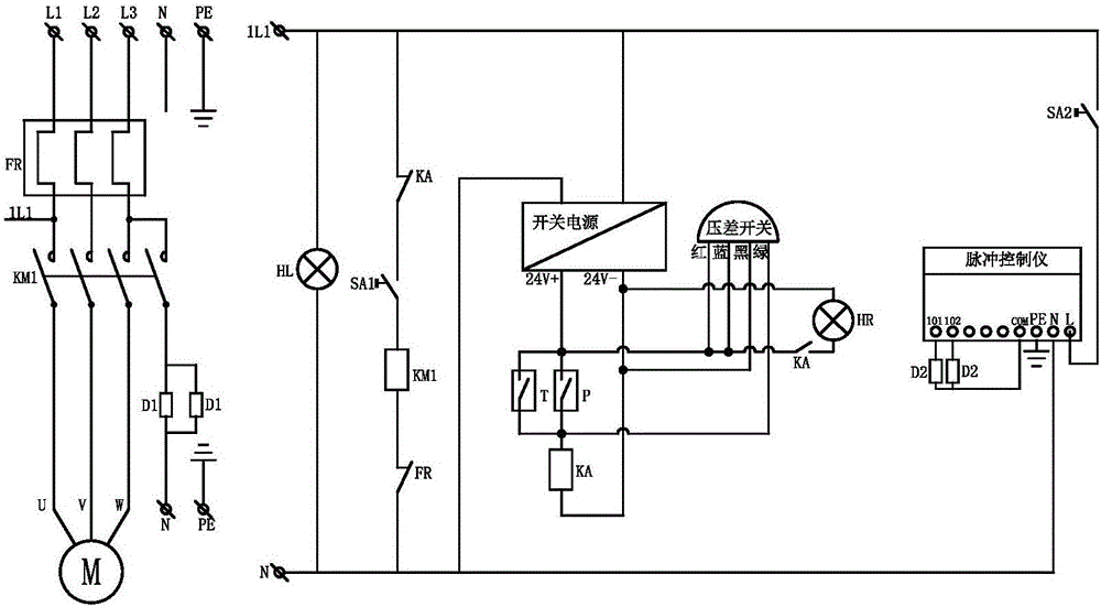
[0041] The structure and principle of this embodiment are basically the same as that of Embodiment 1, and the basic similarities will not be described in detail, only the differences are described. The difference lies in: the fan linkage control circuit of the dust collector also includes The temperature controller T in 5, the temperature detection head of the temperature controller T is installed in the outer area of the filter in the dust removal chamber, and the temperature controller is used for temperature monitoring and alarm in the dust removal chamber. The model of the temperature controller is REXD-C1000. The limit temperature value of the circuit is set in the temperature controller. During the normal operation of the dust collector, the temperature controller monitors the temperature.
[0042] Assume that when the temperature controller T detects that the temperature reaches the set value, the internal switch of the temperature controller T is turned on, the inte...
Embodiment 3
[0044] The structure and principle of this embodiment are basically the same as that of Embodiment 1 and Embodiment 2. The basic similarities will not be described in detail, only the differences will be described. The bottom of the dust removal box 1 is equipped with an ash unloader 6 communicating with the ash outlet. The fan linkage control circuit of the dust collector also includes a proximity switch S arranged on the ash unloader 6 for monitoring whether the ash unloader 6 is running, and the proximity switch S is connected in parallel with the pressure switch P; that is, the result that the ash unloader 6 cannot operate normally The proximity switch S monitors, and then the internal switch of the proximity switch S is turned on, the intermediate relay KA is energized, and then the motor of the fan 2 is also controlled to be powered off, the alarm lamp HR is turned on, and the first solenoid valve D1 is powered off.
PUM
 Abstract
Description
Claims
Application Information
 - R&D
- Intellectual Property
- Life Sciences
- Materials
- Tech Scout
- Unparalleled Data Quality
- Higher Quality Content
- 60% Fewer Hallucinations
Browse by: Latest US Patents, China's latest patents, Technical Efficacy Thesaurus, Application Domain, Technology Topic, Popular Technical Reports.
© 2025 PatSnap. All rights reserved.Legal|Privacy policy|Modern Slavery Act Transparency Statement|Sitemap|About US| Contact US: help@patsnap.com


