Robot kinematic parameter error optimized compensation method and device

A technology of robot kinematics and parameter compensation, which is applied in the fields of instruments, electrical digital data processing, and special data processing applications, and can solve problems such as kinematic inverse analysis failures

Active Publication Date: 2017-02-15
太仓珞石三盛网络科技有限公司 +2
View PDF5 Cites 14 Cited by
  • Summary
  • Abstract
  • Description
  • Claims
  • Application Information

AI Technical Summary

Problems solved by technology

[0005] The purpose of the present invention is to provide a robot kinematic parameter error optimization compensation method and device to solve the problem of kinematic inverse solution analysis failure caused by kinematic parameter compensation

Method used


Image

  • Robot kinematic parameter error optimized compensation method and device
  • Robot kinematic parameter error optimized compensation method and device
  • Robot kinematic parameter error optimized compensation method and device

Examples


Embodiment Construction

[0052] The following will clearly and completely describe the technical solutions in the embodiments of the present invention with reference to the accompanying drawings in the embodiments of the present invention. Obviously, the described embodiments are only some, not all, embodiments of the present invention. The components of the embodiments of the invention generally described and illustrated in the figures herein may be arranged and designed in a variety of different configurations. Accordingly, the following detailed description of the embodiments of the invention provided in the accompanying drawings is not intended to limit the scope of the claimed invention, but merely represents selected embodiments of the invention. Based on the embodiments of the present invention, all other embodiments obtained by those skilled in the art without making creative efforts belong to the protection scope of the present invention.

[0053] In the prior art, the process of compensating...


PUM


Abstract

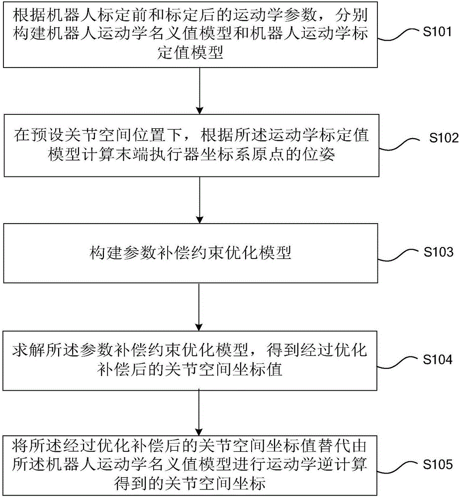
The invention relates to the field of robot parameter correction technologies, in particular to a robot kinematic parameter error optimized compensation method and a robot kinematic parameter error optimized compensation device. The robot kinematic parameter error optimized compensation method comprises the steps of: constructing a robot kinematic nominal value model according to robot kinematic parameters before calibration, and constructing a robot kinematic calibration value model according to robot kinematic parameters after calibration; calculating a pose of an end effector coordinate system origin according to the robot kinematic calibration value model at a preset joint spatial position; constructing a parameter compensation constrained optimization model, wherein the parameter compensation constrained optimization model is used for constraining a difference value between the pose of the end effector coordinate system origin and a preset object pose to be minimum; and calculating the parameter compensation constrained optimization model to obtain joint spatial coordinate values after optimized compensation. The robot kinematic parameter error optimized compensation method and the robot kinematic parameter error optimized compensation device can solve the problem of inverse kinematics analysis failure caused after the compensation of the kinematic parameters.

Description

technical field [0001] The invention relates to the technical field of robot parameter correction, in particular to a method and device for optimizing and compensating robot kinematics parameter errors. Background technique [0002] With the development of technology, the application of industrial robots is becoming more and more popular. At present, the repetition accuracy of industrial robots is relatively high, but the positioning accuracy is relatively poor. Therefore, in many applications, it is necessary to calibrate the relevant parameters of the robot. The so-called calibration refers to the use of relevant measurement methods and appropriate parameter identification methods to identify the exact parameters of the robot model. [0003] Robot kinematics calibration is a commonly used robot parameter calibration method. This method re-identifies and corrects the kinematics parameters of the robot through the steps of modeling, measurement, identification and compensa...

Claims


Application Information

Patent Timeline
IPC IPC(8): G05B23/02G06F17/50
CPCG05B23/0254G06F30/367
Inventor 张博刘大峰黄愐
Owner 太仓珞石三盛网络科技有限公司
Why Eureka
Try Eureka