Laser displacement sensor position error calibration method

A laser displacement and error calibration technology, applied in the field of robotics, can solve the problems of low calibration accuracy and insufficient utilization, and achieve the effect of high calibration accuracy and simple method

Inactive Publication Date: 2017-12-29
BEIHANG UNIV
View PDF3 Cites 13 Cited by
  • Summary
  • Abstract
  • Description
  • Claims
  • Application Information

AI Technical Summary

Problems solved by technology

At present, the existing method is to directly calibrate the installation position. This calibration method does not make full use of the nominal installation position data, which leads to low calibration accuracy. Therefore, the calibration accuracy can be better improved by calibrating the error of the installation position.

Method used


Image

  • Laser displacement sensor position error calibration method
  • Laser displacement sensor position error calibration method
  • Laser displacement sensor position error calibration method

Examples


Embodiment approach

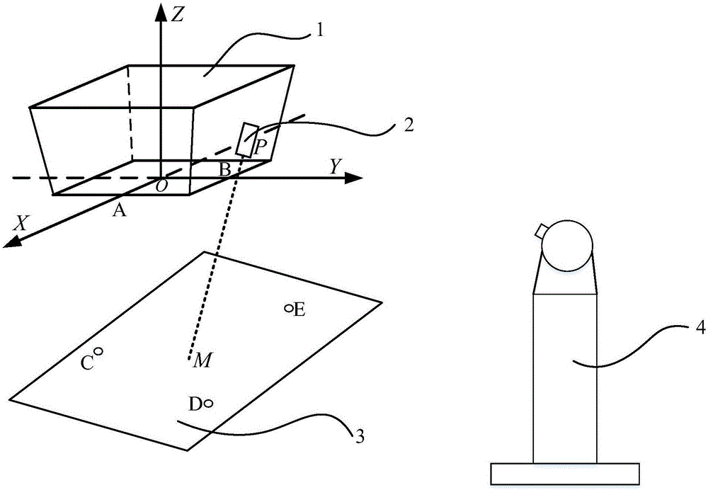
[0022] see figure 1 , The device used in the present invention consists of a mount 1, a laser displacement sensor 2, a flat plate 3 and a laser tracker 4. The laser displacement sensor 2 is installed on the mount 1 .

[0023] The steps of the method of the present invention are described in detail below.

[0024] The specific implementation steps of the inventive method are as follows:

[0025] Step 1: Set up the laser tracker 4 on the ground, so that the mounting base 1 and the panel 3 are included in the measurement range of the laser tracker 4;

[0026] Step 2: Fix the mount 1, and the laser tracker 4 measures the three reference holes A, O and B on the mount 1, and establishes the measurement coordinate system OXYZ, where the hole O is the origin, OA is the X axis, and OB is Y axis, determine the Z axis according to the right-hand rule;

[0027] Step 3: Use the laser tracker 4 to measure the three reference holes C, D and E on the plane plate 3, and then establish the ...


PUM


Abstract

The invention discloses a laser displacement sensor position error calibration method, and belongs to the technical field of robots. The used device is composed of an installing base, a laser displacement sensor, a surface plate and a laser tracker. The laser displacement sensor is installed on the installing base. According to the method, a laser displacement sensor installation position error model is established, and the position error model parameters are identified by using the least square method through data acquisition of the laser tracker and other sensors so that accuracy reduction caused by the installation position error of the laser displacement sensor can be eliminated. The method has the advantages of being simple in method and high in calibration accuracy.

Description

technical field [0001] The present invention relates to robot technology, more specifically, the present invention relates to a method for calibrating the position error of a laser displacement sensor based on the least square method. Background technique [0002] Surface normal measurement has been widely used in aviation drilling robots, and normal measurement by laser displacement sensor is a common measurement method. Due to the influence of the installation error of the laser displacement sensor, there is a certain difference between the actual installation position of the laser displacement sensor and the theoretical installation, which leads to a decrease in the measurement accuracy of the laser displacement sensor, which in turn leads to a decrease in the measurement accuracy of the surface normal. Therefore, it is of great significance to calibrate the installation position error of the laser displacement sensor. At present, the existing method is to directly calib...

Claims


Application Information

Patent Timeline
Patent Type & Authority Applications(China)
IPC IPC(8): G01B11/03
CPCG01B11/03
Inventor 袁培江陈冬冬曹双倩蔡鹦高雷史震云
Owner BEIHANG UNIV
Why Eureka
Try Eureka