
Optical cable gyroscope scale factor temperature modeling method of inertia measurement device

An inertial measurement device and scaling factor technology, applied in the field of inertial measurement, can solve the problems of long time-consuming, inaccurate models, etc., and achieve the effect of short time-consuming, simple calibration method and universality

Active Publication Date: 2015-05-06
BEIJING AEROSPACE TIMES OPTICAL ELECTRONICS TECH
View PDF5 Cites 13 Cited by
  • Summary
  • Abstract
  • Description
  • Claims
  • Application Information

AI Technical Summary

Problems solved by technology

[0004] The technical problem of the present invention is: to overcome the shortcomings of the existing optical fiber inertial measurement device, such as the inaccurate model and long time consumption of the gyroscope scale factor temperature modeling, and propose a gyroscope fixed angle calibration of the optical fiber inertial measurement device to obtain the standard. The method of the degree factor temperature model, after the calibration of the scale factor temperature model, an accurate rate calibration is performed at room temperature, and the scale factor model of the full temperature range is linearly extrapolated using the accurate scale factor value at room temperature

Method used


Image

  • Optical cable gyroscope scale factor temperature modeling method of inertia measurement device
  • Optical cable gyroscope scale factor temperature modeling method of inertia measurement device
  • Optical cable gyroscope scale factor temperature modeling method of inertia measurement device

Examples


Embodiment Construction

[0031] The present invention will be described in further detail below in conjunction with accompanying drawing and specific implementation, as figure 1 Shown is the temperature modeling method flowchart of the present invention, from figure 1 It can be seen that a method for obtaining a scale factor temperature model by fixed-angle calibration of a fiber optic inertial measurement device gyroscope proposed by the present invention, the specific steps are:

[0032] (1) Place the fiber optic inertial measurement device on the hexahedron tooling, and install the tooling in a thermostat with a turntable, so that the measured axis of the gyroscope is consistent with the axis of the turntable;

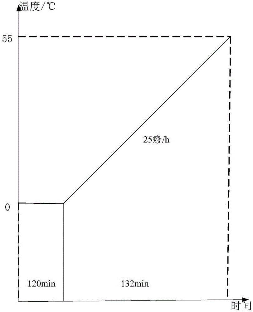
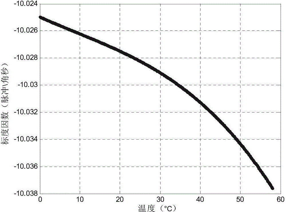
[0033] (2) figure 2 Shown is the rapid temperature rise curve of the incubator implementing the present invention, the scale factor temperature modeling range is 0 ℃ ~ 55 ℃, the optical fiber inertial measurement device is powered on, firstly keep the incubator at 0 ℃ for 2 hours, and mak...


PUM


Abstract

The invention provides an optical cable gyroscope scale factor temperature modeling method of an inertia measurement device. A temperature model of an optical cable gyroscope scale factor is obtained by adopting a constant angle calibrating method in a rapid temperature change environment of a temperature box. The method comprises the following steps that firstly, an inertia measurement device is arranged on a rotary platform temperature box by a hexahedron tool so that a tested shaft of a gyroscope is consistent with a rotary platform shaft; low-temperature-point heat preservation is set in the temperature box and the heat preservation time meets a gyroscope optical path temperature to reach heat balance; a rapid temperature rise mode is set by the temperature box from a low temperature point to a high temperature point; the rotary platform is set to a position mode and the rotary platform rotates for integral circles in front and back directions at a constant rotary speed; angle values of all the rotation circles are divided by a pulse increment value output by two times of rotation in the front and back directions of the gyroscope to obtain a scale factor; and a plurality of groups of scale factors under different temperature points are obtained in a rapid temperature rise process of the temperature box, and are subjected to least square fit to obtain a scale factor temperature model. The modeling method has short operation time and an accurate model; and the rapid and accurate modeling of the optical cable gyroscope scale factors in the inertia measurement device can be realized better.

Description

technical field [0001] The invention relates to a scaling factor temperature modeling method, in particular to a gyroscope scaling factor temperature modeling method of an optical fiber inertial measurement device, which is suitable for high-precision calibration of the full temperature scaling factor of the gyroscope of an optical fiber inertial measurement device, and belongs to inertial measurement technology field. Background technique [0002] The scale factor of the fiber optic gyroscope in the fiber optic inertial measurement device is generally obtained by calibration of the rate turntable. The parameter of the fiber optic gyroscope scale factor is closely related to the temperature field of the position where the fiber optic gyroscope is located. In addition to the self-heating of the gyroscope in the inertial measurement device, Other instruments and circuits around it will also generate heat. At this time, the scale factor of the fiber optic gyroscope will change ...

Claims


Application Information

Patent Timeline
Patent Type & Authority Applications(China)
IPC IPC(8): G01C25/00
CPCG01C25/005
Inventor 邢辉黄继勋向政张红马晓洁郑极石李美清
Owner BEIJING AEROSPACE TIMES OPTICAL ELECTRONICS TECH
Learn More