Raman fiber amplifier gain compensation and transient control method

A technology of amplifier gain and Raman fiber, which is applied in the field of optical communication, can solve problems such as unrealistic gain flatness, gain slope change, and no consideration of input power, etc., and achieves wide application, simple calibration and control methods, and convenient and reliable implementation. Effect

Active Publication Date: 2015-10-21
WUXI TACLINK OPTOELECTRONICS TECH CO LTD
View PDF8 Cites 14 Cited by
  • Summary
  • Abstract
  • Description
  • Claims
  • Application Information

AI Technical Summary

Problems solved by technology

However, as the number of wavelengths in the transmission system increases, the input power also increases, causing the RFA working range to exceed the small signal amplification area. Once the input power changes, the constant pump power operating mode cannot guarantee constant gain control. At this time, the gain needs to be compensated accordingly
[0007] The gain medium of the RFA is the transmission fiber itself, and its length is relatively long (even for a discrete RFA, the length of the gain fiber is basically more than 5km), so there is only one power monitor in the RFA module, so the gain of the EDFA cannot be used Control method (gain control based on the monitoring results of the input and output monitors) for gain compensation and transient control
[0008] The document with the publication number CN102307068A describes a method for Raman gain locking through out-of-band ASE, but this patent only considers the mathematical relationship between Raman gain and ASE, without considering the influence of input power, so this patent is only suitable for input light RFA with constant power
[0009] The document with the publication number CN200510067689.0 mainly introduces the method of Raman gain adjustment when the input optical power changes, but it is realized by two power monitors, which is unrealistic in the actual transmission system; and the patent only changes the shortest The wavelength pump power is used to achieve gain compensation. At this time, the total gain can be kept unchanged, but the gain will be flat and the gain slope will change, and bit errors may occur at the signal receiving end.

Method used


Image

  • Raman fiber amplifier gain compensation and transient control method
  • Raman fiber amplifier gain compensation and transient control method
  • Raman fiber amplifier gain compensation and transient control method

Examples


Embodiment Construction

[0033] The present invention will be further described below in conjunction with specific drawings and embodiments.

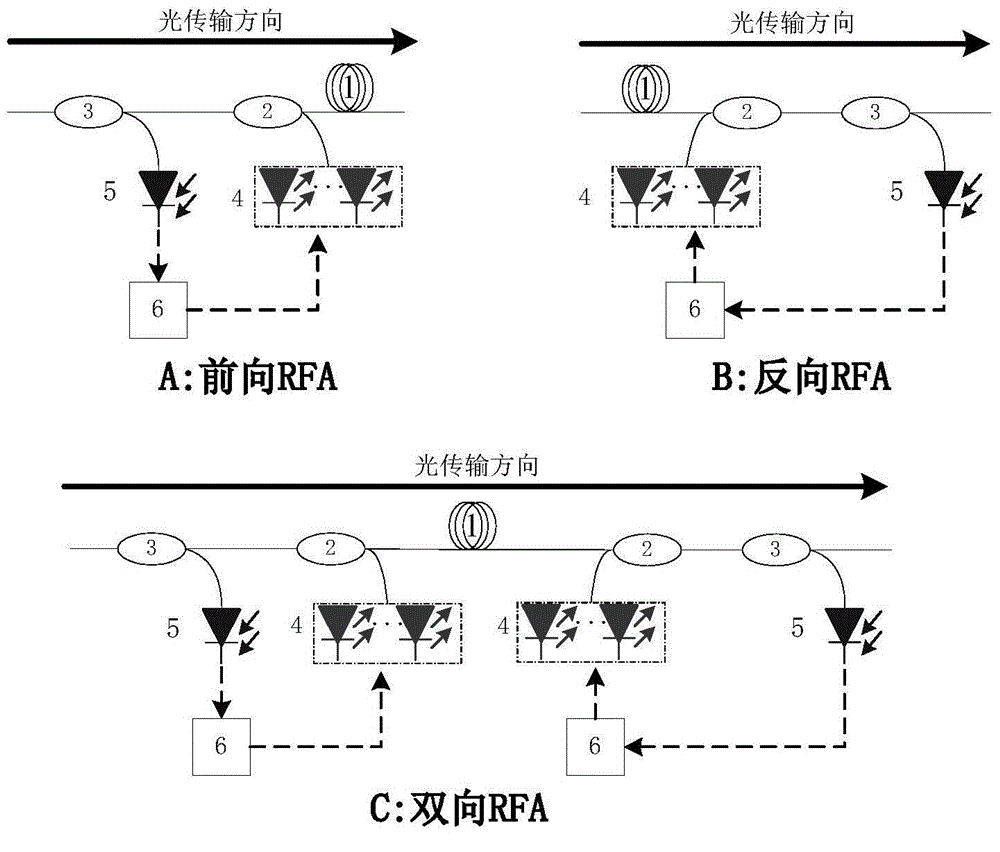
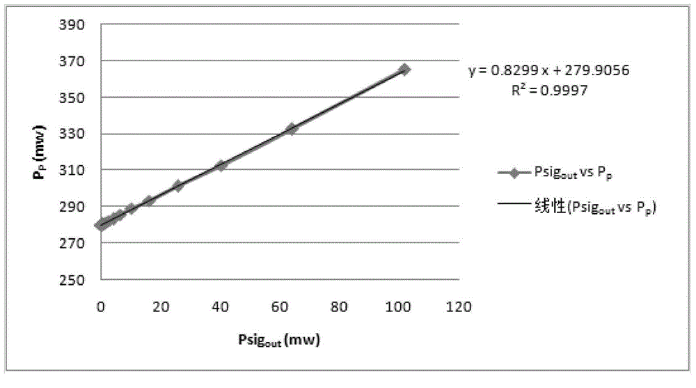
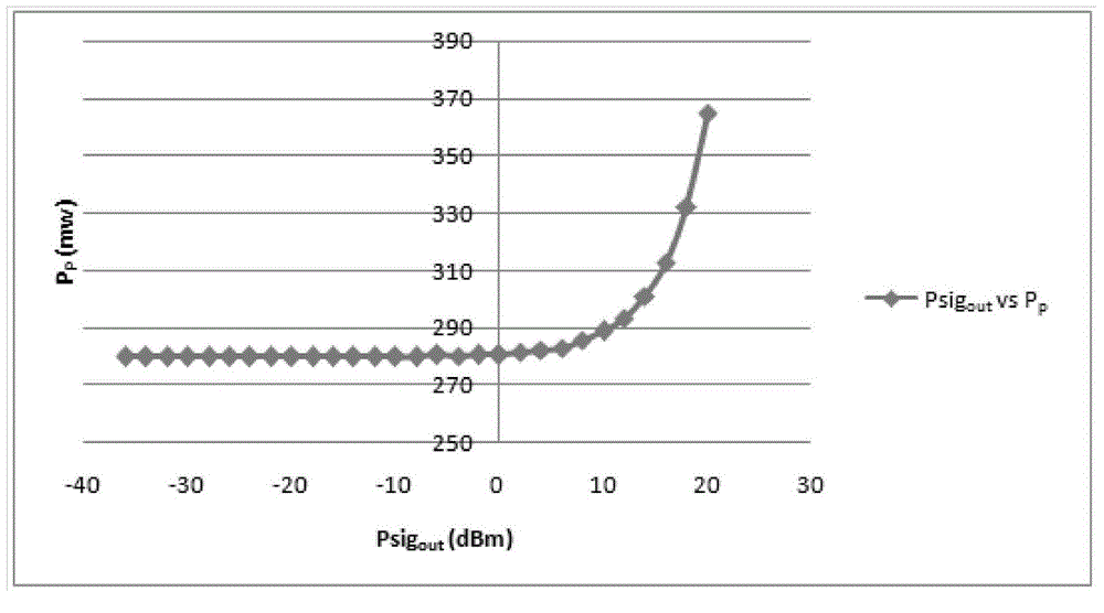
[0034] Such as figure 1 Shown: to the RFA that the pump laser group works in constant power mode, when the input optical power changes in a large range, in order to realize the gain compensation of forward, backward, bidirectional Raman amplifier, the Raman fiber amplifier gain compensation of the present invention And the transient control method is specifically: when the pump laser group in the Raman fiber amplifier works in a constant power mode and the pump laser group is in a locked output power state, determine the input power or output of the Raman fiber amplifier power variation, and adjust the power of the pump laser group according to the variation of input power or output power, so that the power variation of the pump laser group and the variation of input power or output power satisfy ΔP P =k*ΔPtotal, where ΔP p is the power change of the pump las...


PUM


Abstract

The invention relates to a Raman fiber amplifier gain compensation and transient control method. According to the Raman fiber amplifier gain compensation and transient control method, a pump laser set in a Raman fiber amplifier works in a constant power mode, and when the pump laser set is in a locked output power state, the change in input power or output power of the Raman fiber amplifier is determined, and the power of the pump laser set is adjusted according to the change in input power or output power in order to enable the change in power of the pump laser set and the change in input power or output power to meet the formula deltaPp=k*deltaPtotal, wherein deltaPp is the change in power of the pump laser set and the unit is mw, deltaPtotal is the change in input power or output power and the unit is mw, and k is correction slope. For a Raman fiber amplifier of which the pump laser set works in a constant power mode, when the input optical power changes in a large range, forward, backward and two-way Raman amplifier gain compensation can be realized.

Description

technical field [0001] The invention relates to a method, which is a Raman optical fiber amplifier gain compensation and transient control method, and belongs to the technical field of optical communication. Background technique [0002] Raman Fiber Amplifier (RFA: Raman Fiber Amplifier) ​​has a low noise figure, and it can be used in conjunction with Erbium-doped Optical Fiber Amplifier (EDFA: Erbium-doped Optical Fiber Amplifier) ​​to optimize the Optical Signal-to-Noise Ratio (OSNR: Optical Signal Noise Ratio), reducing Small bit error rate and increased transmission distance are widely used in long-distance optical communication transmission systems. [0003] For a certain pump wavelength, the small-signal switching gain of the RFA can be expressed by Equation (1): [0004] G on / off = exp ( g R ...

Claims


Application Information

Patent Timeline
Patent Type & Authority Applications(China)
IPC IPC(8): H04B10/293H01S3/30H01S3/067
Inventor 王雷
Owner WUXI TACLINK OPTOELECTRONICS TECH CO LTD
Why Eureka
Try Eureka