Shock wave time calibration device and method for shock test

A time calibration and impact test technology, applied in the field of impact compression loading, can solve the problems of limited ignition peak pressure of gunpowder and small adjustment range of projectile speed, and achieve the effect of convenient calibration method, simple device structure, and reliable and effective experimental data.

Active Publication Date: 2019-01-22
SOUTHWEST JIAOTONG UNIV
View PDF9 Cites 13 Cited by
  • Summary
  • Abstract
  • Description
  • Claims
  • Application Information

AI Technical Summary

Problems solved by technology

The artillery device is simple, but due to the limited peak pressure that the powder chamber can withstand when the powder is ignited, the average pressure allowed at the bottom of the artillery projectile generally does not exceed 150MPa, so the speed adjustment range of the projectile is very small, only 1km / s~2km / s

Method used


Image

  • Shock wave time calibration device and method for shock test
  • Shock wave time calibration device and method for shock test

Examples


Embodiment

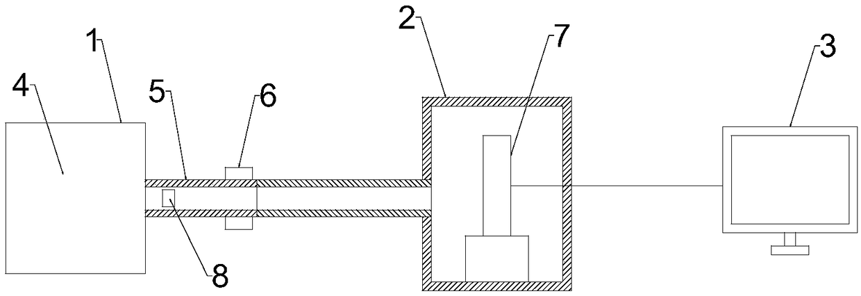
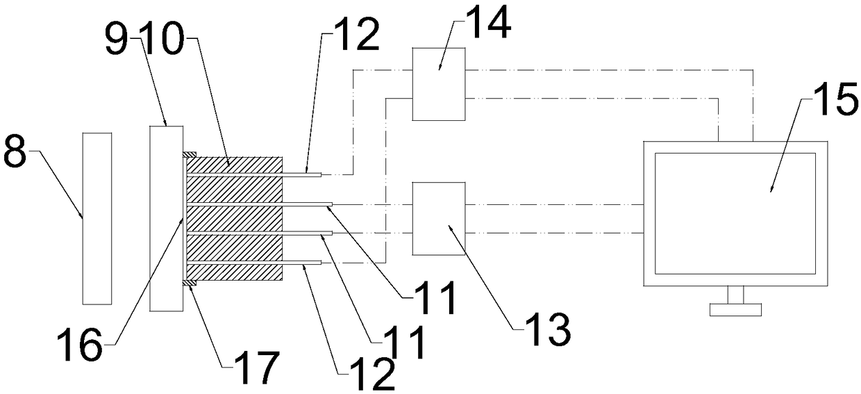
[0028] A shock wave time calibration device for shock testing, such as figure 1 and figure 2 As shown, it includes a controllable high-speed emission device 1, a target chamber 2, and a signal collection device 3. The target chamber 2 is a vacuum target chamber, and an experimental target 7 is arranged in the target chamber 2. The experimental target 7 includes a substrate 9, Fixed column 10, at least one optical probe 11, and at least two electrical probes 12, the fixed column 10 is arranged on the right side wall of the substrate 9 (of course, the fixed column 10 can also be arranged on the left side of the substrate 9 On the side wall, when it is arranged on the left side wall of the substrate 9, the follow-up controllable high-speed launching device 1 is used to drive the right side wall of the flying piece 8 impacting the substrate 9.), the substrate 9 and the fixed column 10 is provided with a light-emitting gap 16, one end of the optical probe 10 and one end of the el...


PUM

PropertyMeasurementUnit
sizeaaaaaaaaaa

Abstract

The invention relates to the technical field of impact compression loading, in particular to a shock wave time calibration device and method for a shock test. The calibration device comprises a controllable high-speed emitting device, a target chamber and a signal collecting device, wherein the target chamber is a vacuum target chamber; an experiment target is arranged in the target chamber; the experiment target comprises a substrate, a fixed column, an optical probe and an electric probe; a light-emitting gap is formed between the substrate and the fixed column; the optical probe and the electric probe are connected with the signal collecting device; and the controllable high-speed emitting device is used for driving a flyer to impact the left side wall of the substrate. According to thecalibration device and method, two waveforms generated according to signals detected by the electric probe and the optical probe are comparatively analyzed, and a more accurate waveform data graph isselected to finally judge a time point when a shock wave enters a sample, so that an important parameter, namely, the time point when the shock wave enters the sample can be more accurately calibrated, and follow-up experiment data is more reliable and effective.

Description

technical field [0001] The invention relates to the technical field of shock compression loading, in particular to a shock wave time calibration device and a time calibration method for shock tests. Background technique [0002] Dynamic ultra-high pressure technology and its theory were developed and matured in the late period of World War II. Its task is usually to study the mechanical properties of solid targets under dynamic ultra-high pressure conditions. [0003] When an extremely strong shock wave (shock wave) propagates in a medium (mainly referring to a solid), it will cause a sharp change in the state parameters of the medium such as pressure, density, and temperature. This state is called a dynamic ultra-high pressure state, and the technology of generating strong shock waves is called a dynamic ultra-high pressure technology. Dynamic ultra-high pressure technology is used in the measurement of the equation of state, artificial synthesis of new materials (such as...

Claims


Application Information

Patent Timeline
Patent Type & Authority Applications(China)
IPC IPC(8): G01N3/02G01N3/307
CPCG01N3/02G01N3/307G01N2203/001G01N2203/0044
Inventor 范茁宁蒋城露李若曦汪贻高秦涵刘其军张明建刘福生樊代和常相辉
Owner SOUTHWEST JIAOTONG UNIV
Why Eureka
Try Eureka