Timing method, device and system

A technology of timers and statistical institutes, applied in the directions of calculation, time register, recording/indicating the time of events, etc., can solve the problems of inaccuracy, inability to apply to internal combustion industrial vehicles, incomplete timing results, etc., to achieve convenient device installation, The effect of reducing equipment costs, ensuring integrity and accuracy

Inactive Publication Date: 2017-02-15
SUZHOU YIXINAN IND TECH CO LTD
View PDF4 Cites 8 Cited by
  • Summary
  • Abstract
  • Description
  • Claims
  • Application Information

AI Technical Summary

Problems solved by technology

[0006] In view of this, the present application provides a timing method, device and system, which solves the technical problem that the prior art timin...

Method used


Image

  • Timing method, device and system
  • Timing method, device and system
  • Timing method, device and system

Examples


Embodiment 1

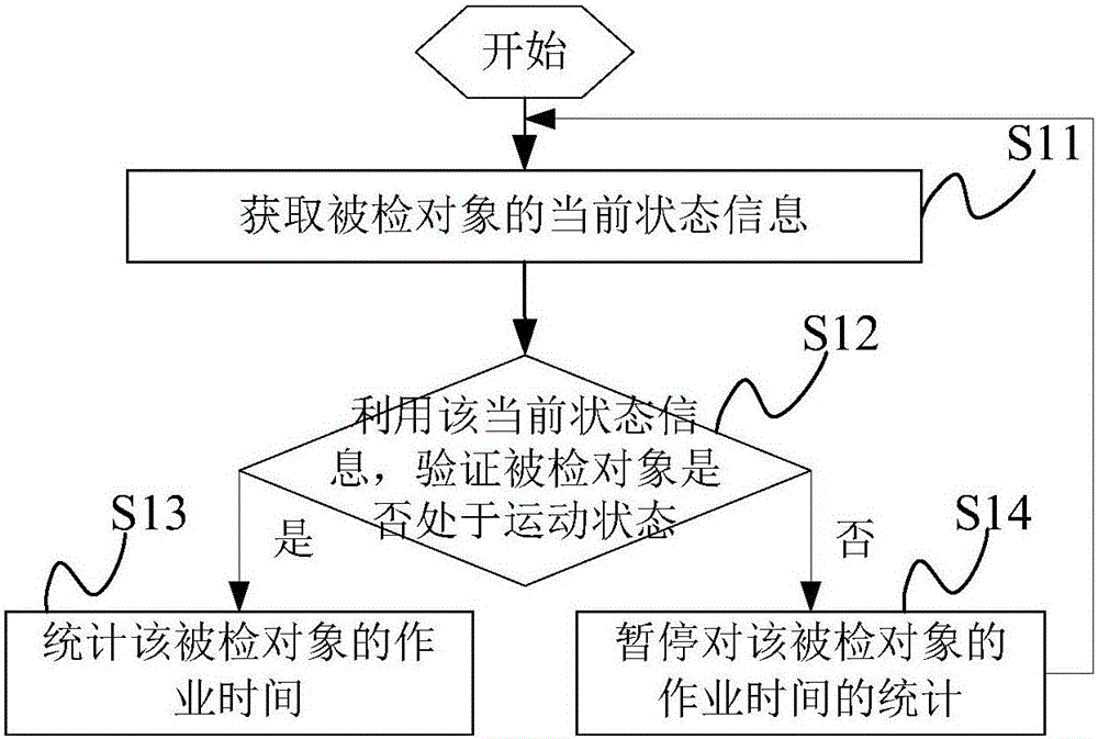
[0074] Such as figure 1 As shown, the flow chart of Embodiment 1 of a timing method provided in this application, the method may include the following steps:

[0075] Step S11: Obtain current status information of the inspected object.

[0076] Among them, the inspected object may be an industrial vehicle such as a forklift, and this application does not limit the specific structure of the inspected object.

[0077] In this embodiment, in order to be able to grasp the work status of the inspected object, the current state information of the inspected object can be detected in real time. This application does not limit the detection method of the current state of the inspected object, where the current state information can be Indicate the current state of the inspected object, such as moving state, static state, etc.

[0078] Based on this, the current state information obtained in the above step S11 may include acceleration change information, vibration intensity, speed information d...

Embodiment 2

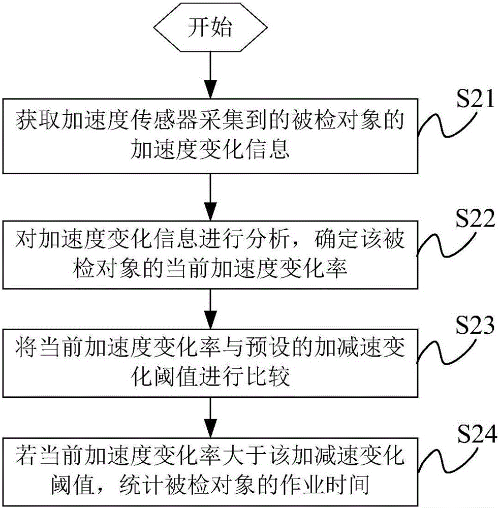
[0091] Such as figure 2 As shown, the flow chart of the second embodiment of a timing method provided for this application, this embodiment is actually a specific implementation method for timing the task of the inspected object, and the method may include the following steps:

[0092] Step S21: Acquire the acceleration change information of the detected object collected by the acceleration sensor.

[0093] In practical applications, this embodiment can collect acceleration change information of the inspected object through an acceleration sensor. Since the acceleration sensor can be directly fixed at any position of the inspected object, the installation position of the acceleration sensor is not limited in this application. It can be seen that, compared with the existing installation process of each detection device, the installation process of the detection device is greatly simplified, and the equipment cost is reduced.

[0094] Step S22: Analyze the acceleration change informa...

Embodiment 3

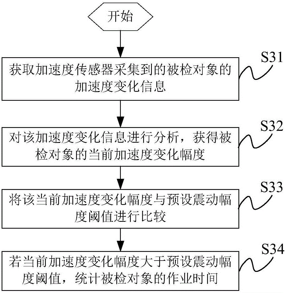
[0109] Such as image 3 As shown, the flow chart of Embodiment 3 of a timing method provided by this application. This embodiment and the above-mentioned Embodiment 2 both use acceleration change information collected by an acceleration sensor to implement job timing. The only difference is to determine whether the inspected object is The specific process of being in motion is as follows:

[0110] Step S31: Obtain the acceleration change information of the detected object collected by the acceleration sensor.

[0111] For the process of obtaining the acceleration change information, reference may be made to the description of the corresponding part of the foregoing embodiment, which is not repeated in this embodiment.

[0112] Step S32: Analyze the acceleration change information to obtain the current acceleration change range of the object under inspection.

[0113] In the actual work process of the inspected object, due to work needs, affected by the road surface, etc., the accelera...


PUM


Abstract

The application provides a timing method, device and system. The application timely obtains information of the current state of a detected object and then determines whether the detected object is in a moving state or not based on the information of the current state, so that statistics of working time of the detected object is achieved. Therefore, the application does not need to detect change in current and/or voltage of a motor of the detected object and change in liquid pressure or a rotation device, and the application is suitable for operation timing of an internal combustion industrial vehicle while voltage, current, liquid pressure and externally-installed devices such as proximity switches are not required, so that the device installation is enabled to be more convenient, and the equipment cost is lowered. In addition, the application can accurately determine the detected object is in a static or non-working state, or a working state, or the like, so that timing of the whole working of the detected object is achieved, and the integrity and the accuracy of the timing result are ensured.

Description

Technical field [0001] This application is mainly applied to the field of equipment management applications, and more specifically relates to a timing method, device and system. Background technique [0002] Industrial vehicles refer to power-driven motor vehicles used to carry, push, haul, lift, stack or stack various goods, such as the commonly used forklifts, which are the main force in material handling equipment and have been widely used To various sectors of the national economy such as stations, ports, airports, factories, warehouses, etc. [0003] In practical applications, the working time of industrial vehicles is usually monitored, so as to obtain information such as the effective working time of industrial vehicles and the actual working time of the staff, and then use the detected data to analyze the working conditions of the staff. To achieve performance management, it can also analyze the utilization rate of industrial vehicles, so as to adjust the working range of ...

Claims


Application Information

Patent Timeline
IPC IPC(8): G06Q10/06G07C1/02
CPCG06Q10/063114G06Q10/06312G06Q10/06393G07C1/02
Inventor 李恒朱创宇刘亮
Owner SUZHOU YIXINAN IND TECH CO LTD
Why Eureka
Try Eureka