
A power distribution cabinet

A power distribution cabinet and power technology, applied in substation/distribution device casing, electrical components, substation/switch layout details, etc., can solve the problems of single placement of power distribution cabinets, difficult to meet power distribution needs, and inflexible operation. , to achieve the effect of good positioning effect, simple and reliable positioning method, and labor-saving and convenient movement.

Inactive Publication Date: 2018-11-02
STATE GRID CORP OF CHINA +1
View PDF5 Cites 0 Cited by
  • Summary
  • Abstract
  • Description
  • Claims
  • Application Information

AI Technical Summary

Problems solved by technology

[0002] The use of power equipment and power transmission equipment is inseparable from the use of power distribution cabinets. Power distribution cabinets provide great convenience for power deployment and are an important power facility. However, traditional power distribution cabinets In use, the placement method is single, the rotation is inconvenient, and the operation is not flexible enough, so that the power distribution cabinet will encounter many problems during installation and maintenance, and the power distribution cabinet is used as a single unit, sometimes it is difficult to meet the complex power distribution requirements.

Method used


Image

  • A power distribution cabinet
  • A power distribution cabinet
  • A power distribution cabinet

Examples


Embodiment Construction

[0017] The following will clearly and completely describe the technical solutions in the embodiments of the present invention with reference to the accompanying drawings in the embodiments of the present invention. Obviously, the described embodiments are only some, not all, embodiments of the present invention. Based on the embodiments of the present invention, all other embodiments obtained by persons of ordinary skill in the art without making creative efforts belong to the protection scope of the present invention.

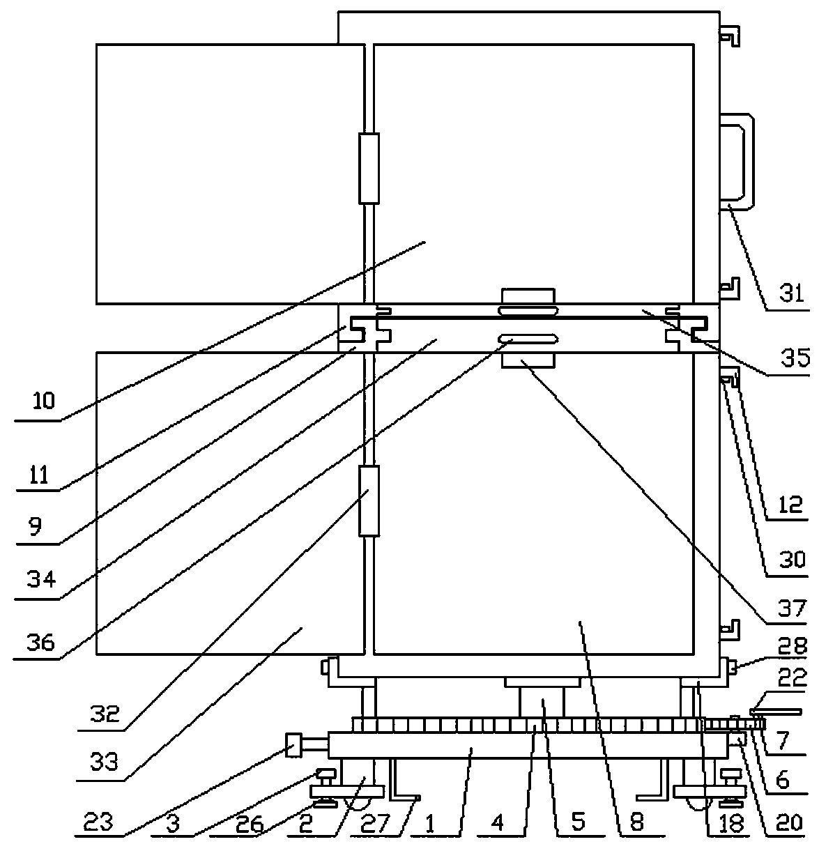
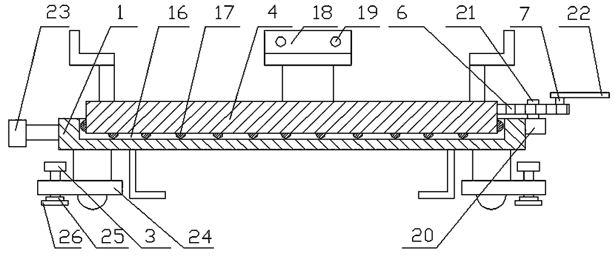
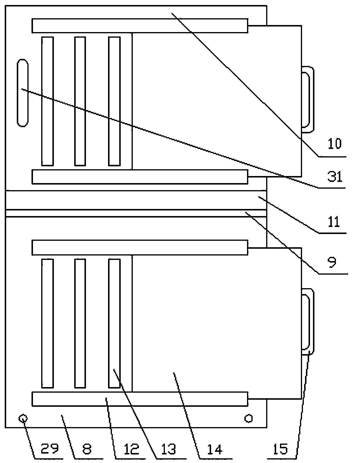
[0018] see Figure 1-3 , the present invention provides a technical solution: a power distribution cabinet, including a device base 1, a universal wheel 2 is provided on the lower part of the device base 1, and a positioning bolt 3 is provided on one side of the universal wheel 2, and the The upper part of the device base 1 is rotatably provided with a main turntable 4, the upper part of the main turntable 4 is provided with a group of pillars 5, and the side ...


PUM


Abstract

The invention discloses an electric power distribution cabinet, which comprises a device base, wherein the lower part of the device base is provided with universal wheels, one side of each universal wheel is provided with a positioning bolt, the upper part of the device base is provided with a main turntable in a rotated manner, the upper part of the main turntable is provided with a group of supporting columns, one side of the device base is provided with a driving gear, a rotating rod is arranged on the driving gear, the driving gear is engaged with the main turntable, the upper parts of the supporting columns are connected with a lower box body, a box body slideway is arranged on the upper part of the lower box body, the box body slideway is in sliding fit with a sliding rail arranged at the lower part of an upper box body, the side parts of the upper box body and the lower box body are each provided with baffle plate slideways, heat radiating holes are formed in the side parts of the upper box body and the lower box body, and the baffle plate slideways are in sliding fit with baffle plates. The electric power distribution cabinet is convenient to move, can rotate flexibly, has good heat radiating and moisture-proof functions, can accommodate more power accessories, and has higher applicability.

Description

technical field [0001] The invention relates to the field of power distribution cabinets, in particular to a power distribution cabinet. Background technique [0002] The use of power equipment and power transmission equipment is inseparable from the use of power distribution cabinets. Power distribution cabinets provide great convenience for power deployment and are an important power facility. However, traditional power distribution cabinets In use, the placement method is single, the rotation is inconvenient, and the operation is not flexible enough, so that many problems will be encountered in the installation and maintenance of the power distribution cabinet, and the power distribution cabinet is used as a single unit, and sometimes it is difficult to meet the complex power distribution requirements. . Contents of the invention [0003] The purpose of the present invention is to provide a power distribution cabinet to solve the problems raised in the above-mentioned ...

Claims


Application Information

Patent Timeline
Patent Type & Authority Patents(China)
IPC IPC(8): H02B1/56H02B1/52H02B1/30H02B1/28
CPCH02B1/28H02B1/303H02B1/52H02B1/565
Inventor 李强王大军邢丽美王芳郑伟刘国强张文韬刘扬秦聪林涛邢浩吕伟于丽梅毕伟翔高学涛
Owner STATE GRID CORP OF CHINA
Learn More