Permanent magnet motor rotor punching with self-starting ability and industrial frequency conversion performance

A technology of rotor punching and permanent magnet motor, applied in the field of electric motor, can solve the problems of cost reduction and efficiency increase, reduction of motor overload capacity, high market promotion price, saving mold material cost and labor cost, improving starting performance, The effect of optimizing the design of the groove size

Active Publication Date: 2018-10-16
SHENYANG POLYTECHNIC UNIV
View PDF6 Cites 0 Cited by
  • Summary
  • Abstract
  • Description
  • Claims
  • Application Information

AI Technical Summary

Problems solved by technology

At present, these two types of motors use different rotor punching structures, which require two sets of molds. The manufacturing cost is high, the production cycle is long, and the corresponding labor cost is also high, which is not conducive to the cost reduction and efficiency increase of enterprises.
[0003] High-performance asynchronous starting permanent magnet synchronous motor must meet high starting quality factor, high efficiency and high power factor at the same time, so the rotor squirrel cage slot and permanent magnet need to have enough design space, such as image 3 As shown, the traditional punching structure often cannot meet such design requirements, and the iron core can only be lengthened to meet the design requirements, which will increase the cost of the motor and cause the market promotion to be limited by the high price
[0004] If the traditional asynchronous start permanent magnet synchronous motor is directly used as a variable frequency speed regulation motor, due to its rotor structure, the magnetic flux often passes through the pole shoes to form a closed magnetic circuit, which will cause the motor to be too saturated, thereby reducing the overload capacity of the motor

Method used


Image

  • Permanent magnet motor rotor punching with self-starting ability and industrial frequency conversion performance
  • Permanent magnet motor rotor punching with self-starting ability and industrial frequency conversion performance
  • Permanent magnet motor rotor punching with self-starting ability and industrial frequency conversion performance

Examples


Embodiment 1

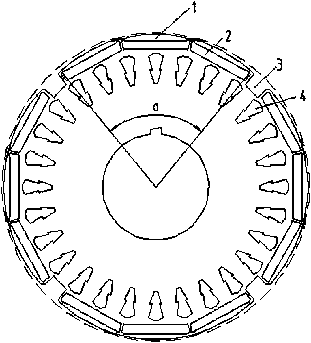
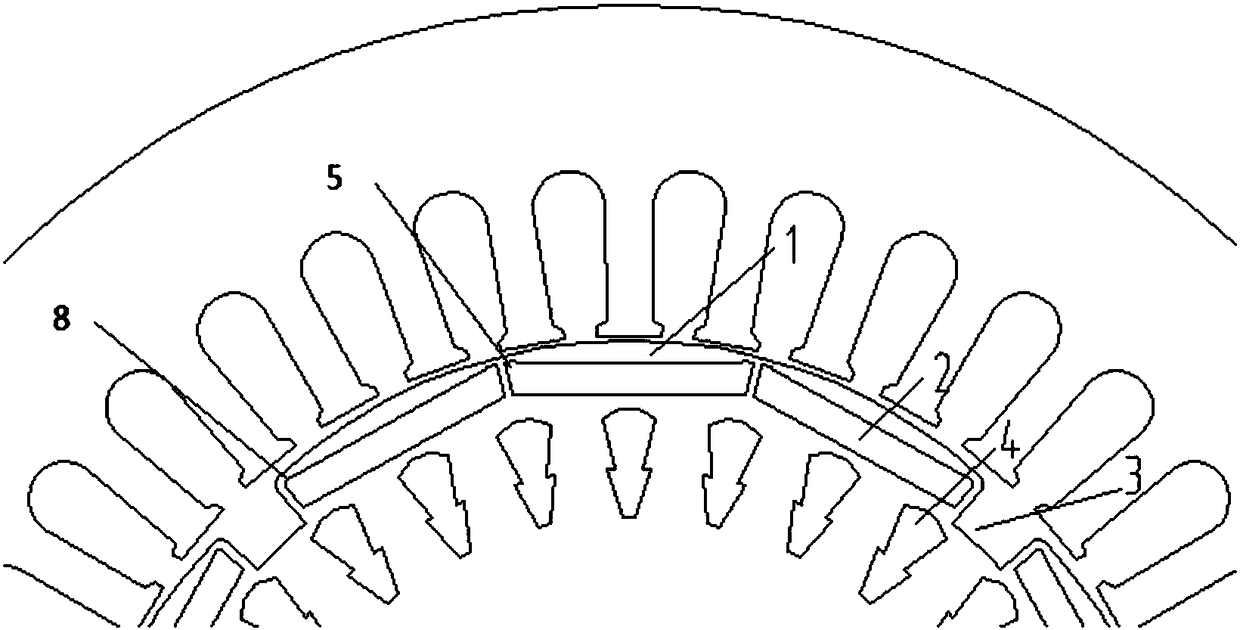
[0035] A permanent magnet motor rotor stamping with self-starting capability and industrial frequency conversion performance, such as figure 1 and figure 2 As shown, the stamping structure includes rotor poles, permanent magnet slots, permanent magnets, slots between poles and evenly distributed slots arranged at the lower part of the permanent magnet slots. The number of punching poles is 4 poles, the number of permanent magnet slots and permanent magnets for each pole is 3 pieces, the magnetic pole angle is 0.75~0.8 times of 360 / 2p, p is the number of pole pairs of the motor, and the outer circle of the magnetic pole is the punching piece with the rotor A circular arc with different concentricity, its radius is (0.89~0.93)×R, R is the radius of the outer circle of the rotor punching piece, and it is set in the evenly distributed slots under the permanent magnet slots.

[0036] Such as figure 1 As shown, in view of the requirements of the load on the starting performance...


PUM


Abstract

The invention discloses a permanent magnet motor rotor stamping with self-starting capability and industrial frequency conversion performance. The stamping structure includes rotor magnetic poles, permanent magnet slots, permanent magnets, slots between poles and a uniform Distributed slots; the number of punching poles is greater than or equal to 2, and the number of permanent magnet slots and permanent magnets per magnetic pole is greater than or equal to 1; the magnetic pole angle is 0.75~0.8 times of 360 / 2p, and p is the number of pole pairs of the motor; the outer circle of the rotor pole It is a circular arc that is not concentric with the rotor punch, and its radius is (0.89~0.93)×R, R is the outer circle radius of the rotor punch; permanent magnets are embedded in permanent magnet slots, and there is an inter-pole gap between adjacent rotor poles. groove.

Description

technical field [0001] The invention relates to the field of electric motors, in particular to a high cost-effective permanent magnet motor rotor punching structure with self-starting capability and excellent operation performance of industrial frequency conversion. Background technique [0002] Permanent magnet motors are generally divided into asynchronous start permanent magnet synchronous motors (with self-starting capability) and variable frequency variable speed permanent magnet synchronous motors according to different starting and operating modes. At present, these two motors use different rotor punching structures, which require two sets of molds. The manufacturing cost is high, the production cycle is long, and the corresponding labor cost is also high, which is not conducive to the cost reduction and efficiency increase of enterprises. [0003] High-performance asynchronous starting permanent magnet synchronous motor must meet high starting quality factor, high ef...

Claims


Application Information

Patent Timeline
Patent Type & Authority Patents(China)
IPC IPC(8): H02K1/27
CPCH02K1/27
Inventor 王瑾高俊陈龙周挺王凯东
Owner SHENYANG POLYTECHNIC UNIV
Why Eureka
Try Eureka