
Driving force controller for electric vehicle

A technology for control devices and electric vehicles, which is applied in the directions of control devices, electric vehicles, and power-consuming devices, can solve problems such as deviation, and achieve the effect of simple structure

Active Publication Date: 2017-02-15
CALSONIC KANSEI CORP
View PDF5 Cites 8 Cited by
  • Summary
  • Abstract
  • Description
  • Claims
  • Application Information

AI Technical Summary

Problems solved by technology

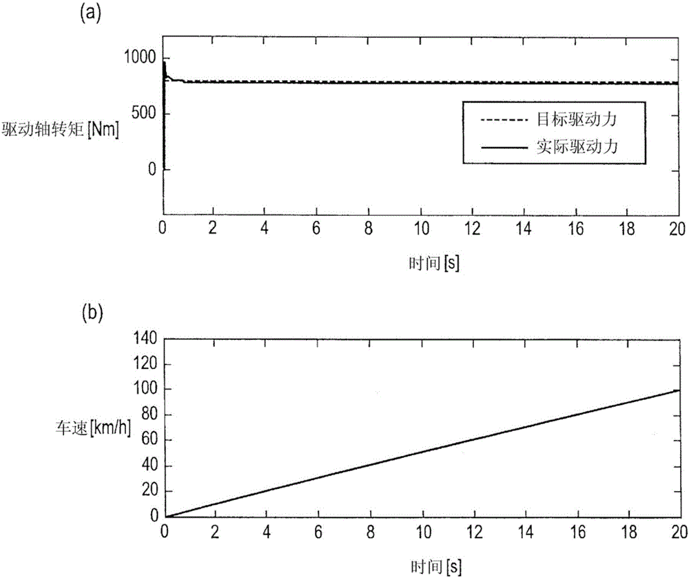
As a result, there is a problem that, although the torsional vibration can be suppressed by the correction value, when running resistance occurs or when braking, excessive driving force is generated so that the running resistance torque and the braking torque generated by the brake operation are also canceled out. As a result, the driver's request deviates from the actual driving force

Method used


Image

  • Driving force controller for electric vehicle
  • Driving force controller for electric vehicle
  • Driving force controller for electric vehicle

Examples


no. 1 approach

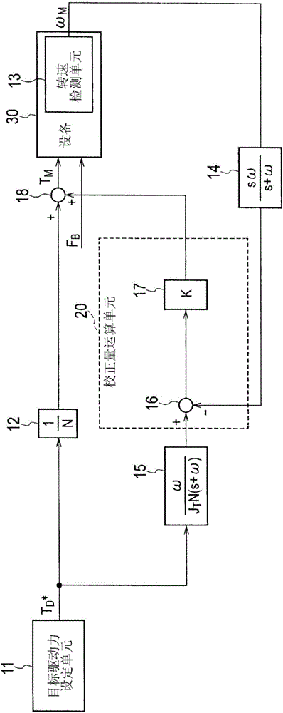
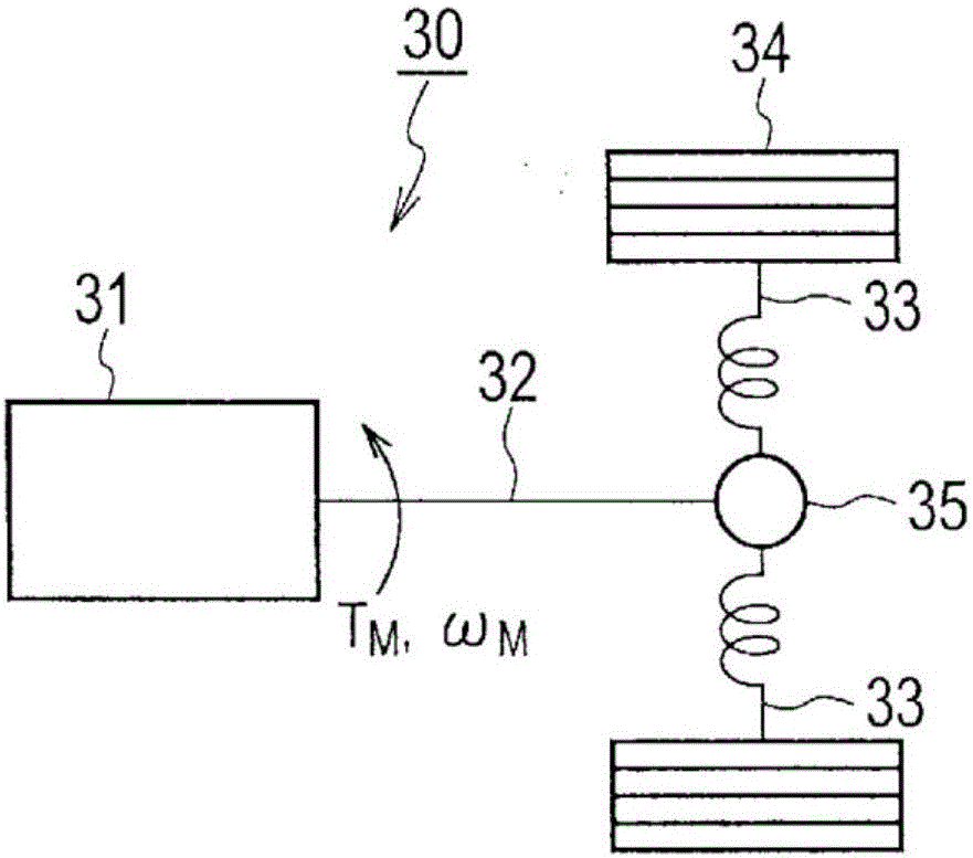
[0022] The driving force control device for an electric vehicle according to the first embodiment of the present invention can be mounted on an electric vehicle such as an electric vehicle (EV). like figure 1 As shown, the drive control device for an electric vehicle according to the first embodiment of the present invention includes a target drive force setting unit 11, a division unit 12, a target acceleration calculation unit 15, an actual acceleration calculation unit 14, a correction amount calculation unit 20 and Instruction value operation unit 18 . Each unit of the drive control device for an electric vehicle according to the first embodiment of the present invention can be constituted by a central processing unit (CPU), a memory, an arithmetic circuit, and the like. The command value calculation unit 18 is connected to a device 30 to be controlled.

[0023] Device 30 is the drive system of an electric vehicle, such as figure 2 As shown, the device 30 has an electr...

no. 2 approach

[0052] In the first embodiment of the present invention, the inertia J of the ideal vehicle model set for calculating the target acceleration T Including motor inertia, vehicle weight and other parameters. For example, the weight of a vehicle is a value that easily changes depending on the number of passengers and the loading amount, so modeling errors often occur. When the inertia J of the ideal vehicle model T When an error occurs, the correction amount has a value even in a stable state where torsional vibration does not occur. Therefore, there is concern that the target driving force T determined by the driver's operation D There is a difference between * and the actual driving force, resulting in discomfort in the sense of acceleration. In addition, in the first embodiment of the present invention, there may be cases where the influence of modeling errors cannot be completely removed.

[0053] Here, a mechanism in which the correction amount has a value in a steady st...


PUM


Abstract

Provided is a driving force controller for an electric vehicle, said controller having a simple configuration, being able to suppress torsional vibrations in a drive system, and being able to suppress the divergence between a target driving force and a real driving force during running-resistance generation and braking. The driving force controller controls the motor driving force in the drive system of an electric vehicle and is provided with: a target driving-force setting means (11) that sets a target driving-force on the basis of a driver request; a division means (12) that calculates a first motor-torque command value by dividing the target driving-force by a reduction ratio; a target acceleration calculation means (15) that calculates a target acceleration by dividing the target driving-force by the drive system inertia; a real acceleration calculation means (14) that calculates the real acceleration by differentiating the real motor speed; a correction amount calculation means (20) that calculates a correction amount that reduces the deviation between the target acceleration and the real acceleration; and a command value calculation means (18) that calculates a second motor-torque command value by adding the correction amount to the first motor-torque command value.

Description

technical field [0001] The invention relates to a driving force control device of an electric vehicle. Background technique [0002] In a conventional driving force control device for an electric vehicle, a motor torque command value set according to a driver's request (target driving force) is corrected in order to suppress vibration (torsional vibration) generated by torsion of a drive system. For example, the target vehicle speed is calculated as a vehicle speed when a motor torque command value is given to an ideal vehicle model in which the drive system is assumed to be a rigid body that does not undergo torsion. Then, the deviation between the target vehicle speed and the actual vehicle speed is obtained, and a correction value for reducing the deviation is calculated. The correction value is added to the motor torque command value to obtain the final motor torque command value. [0003] In the conventional ideal vehicle model, running resistance torque such as air r...

Claims


Application Information

Patent Timeline
Patent Type & Authority Applications(China)
IPC IPC(8): B60L15/20
CPCB60L3/12B60L15/2009B60L2240/423B60L2260/42B60L2270/145Y02T10/64Y02T10/72B60L15/20B60Y2200/91
Inventor 长村谦介岩鼻利幸平田光男
Owner CALSONIC KANSEI CORP
Learn More