Bionic drag reduction potato harvester digging shovel

A digging shovel and harvester technology, which is applied in the field of bionic drag-reducing potato harvester digging shovel, can solve the problems of low efficiency of excavating mechanism, poor ability to break soil, broken soil, and wear of sand and gravel, so as to improve the performance of drag reduction and desorption, The effect of improving the ability to penetrate into the soil and improving the drag reduction performance

Active Publication Date: 2017-02-22
JILIN UNIV
View PDF4 Cites 7 Cited by
  • Summary
  • Abstract
  • Description
  • Claims
  • Application Information

AI Technical Summary

Problems solved by technology

my country has a vast territory, and the soil texture and planting agronomic conditions of potato production areas are different. For example, the soil in Northeast my country is heavy, the soil in Northwest China is rocky, and the soil in South China is sandy. A large number of promotional applications
Compared with foreign potato harvesting machinery, domestic models cannot fully meet the needs of production development. There are three main problems: First, poor reliability
The soil environment of potato harvesting machinery is complex, and the efficiency of a single type of excavating mechanism is low, which cannot meet the basic requirements for use
Second, poor adaptability
Under different soil conditions and different plant conditions, the digg

Method used


Image

  • Bionic drag reduction potato harvester digging shovel
  • Bionic drag reduction potato harvester digging shovel
  • Bionic drag reduction potato harvester digging shovel

Examples


Example Embodiment

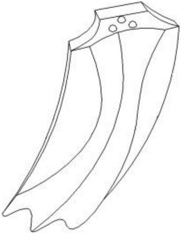
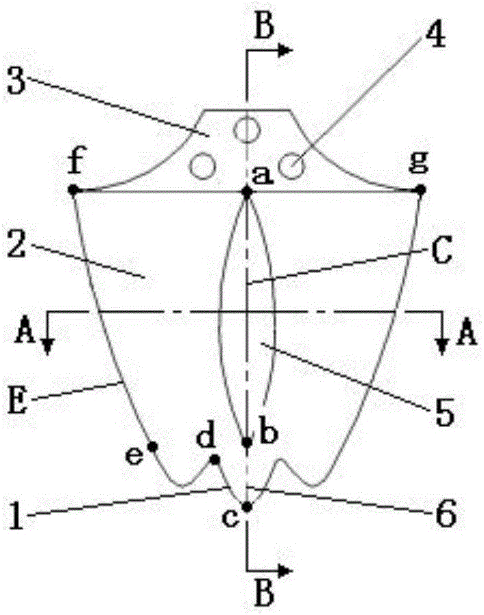
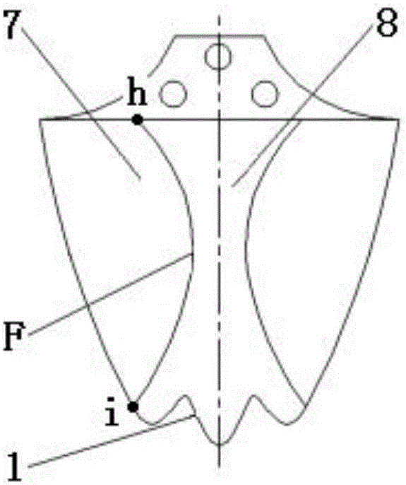
[0025] Such as figure 1 , figure 2 , image 3 The shown bionic drag reduction potato harvester digging shovel is composed of 3 shovel teeth 1, soil-contacting shovel surface I2, shovel handle 3, convex surface 5, soil-contacting shovel surface II7 and recessed surface 8, among which the soil-contacting shovel surface Ⅰ2 and convex surface 5 are located on the front of the shovel, and the convex surface (5) is set in the middle of the soil contact shovel surface I2. The point a of the longitudinal section contour line C in the convex surface 5 coincides with the straight midpoint of the bottom end fg of the shovel handle 3. , The cross-sectional contour line G of the convex surface 5 is the jk curve; the soil contact shovel surface Ⅱ7 and the recessed surface 8 are located on the back side of the shovel, the recessed surface 8 is set in the middle of the soil contact shovel surface Ⅱ7, the soil contact shovel surface I2 and the soil contact shovel The point e of the arc contour ...


PUM


Abstract

The invention discloses a bionic drag reduction potato harvester digging shovel, and belongs to the technical field of agricultural machinery. The bionic drag reduction potato harvester digging shovel is of an integrated structure comprising soil piercing shovel teeth, a soil contact shovel surface I, a shovel handle, a soil contact shovel surface II and a concave surface, a shovel body is arc-shaped, the soil contact shovel surface I and a convex surface are positioned in the front of the digging shovel, the soil contact shovel surface II and the concave surface are positioned at the back of the digging shovel, the convex surface is positioned in the middle of the soil contact shovel surface I, the concave surface is arranged in the middle of the soil contact shovel surface II, the soil piercing shovel teeth are positioned at the front end of the digging shovel, the shovel handle is positioned at the tail end of the digging shovel, the top end of the digging shovel is rectangular, transits to the bottom end by an arc and is fixedly connected with top ends of the soil contact shovel surface I and the soil contact shovel surface II, three triangular sunk screw holes are formed in the shovel handle, the soil piercing wedge angle alpha of the digging shovel ranges from 20 degrees to 45 degrees, and the clearance angle theta of a shovel edge with the soil piercing shovel teeth ranges from 3 degrees to 6 degrees. The digging shovel is high in applicability, the soil piercing capacity and drag reduction and desorption properties of the potato digging shovel can be remarkably improved, and the drag reduction property is improved by 30% or more as compared with a traditional potato digging shovel.

Description

technical field [0001] The invention belongs to the technical field of agricultural machinery, and in particular relates to a digging shovel for a bionic drag-reducing potato harvester. Background technique [0002] The function of the potato digging shovel is to dig out the potato pieces and transport the potato pieces to the separation device. Digging performance is an important index to evaluate the performance of potato harvesting equipment, which is closely related to factors such as harvesting equipment structure, operating parameters, and key component materials. my country has a vast territory, and the soil texture and planting agronomic conditions of potato production areas are different. For example, the soil in Northeast my country is heavy, the soil in Northwest China is rocky, and the soil in South China is sandy. A large number of promotional applications. Compared with foreign potato harvesting machinery, domestic models cannot fully meet the needs of product...

Claims


Application Information

Patent Timeline
IPC IPC(8): A01D13/00
CPCA01D13/00
Inventor 李俊伟马云海毛春昱禹江涛王慧鑫庄健
Owner JILIN UNIV
Why Eureka
Try Eureka